Toyota Tacoma (2015-2018) Service Manual: Disassembly
DISASSEMBLY
PROCEDURE
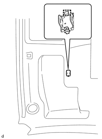
1. REMOVE TELEPHONE MICROPHONE ASSEMBLY
Click here .gif)
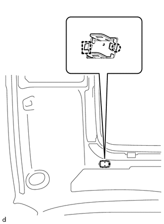
2. REMOVE MICROPHONE CASE
|
(a) w/o Sliding Roof: (1) Disengage the claw and guide to remove the microphone case. |
|
|
(b) w/ Sliding Roof: (1) Disengage the claw and guide to remove the microphone case. |
|
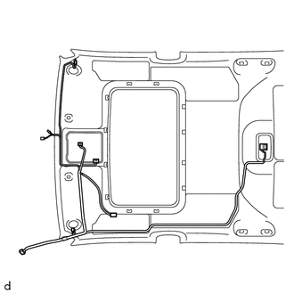
3. REMOVE NO. 1 ROOF WIRE (w/ Sliding Roof)
(a) w/ Vanity Light:
|
(1) w/ EC Mirror:
|
|

|
(2) w/o EC Mirror:
|
|
(b) w/o Vanity Light:
|
(1) w/ EC Mirror:
|
|
|
(2) w/o EC Mirror:
|
|

(c) w/o Toyota Safety Sense P:
|
(1) Remove the No. 1 roof wire. |
|

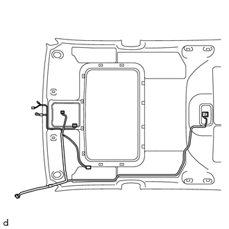
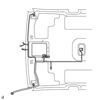
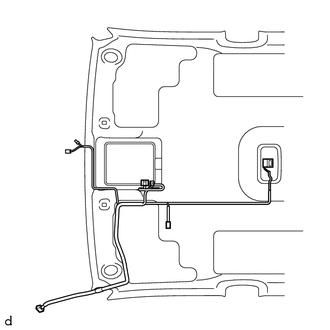
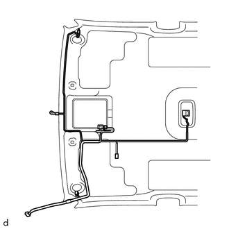
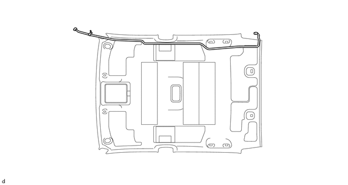
4. REMOVE NO. 1 ROOF WIRE (w/o Sliding Roof)
(a) w/ Vanity Light:
|
(1) w/ EC Mirror:
|
|
|
(2) w/o EC Mirror:
|
|

(b) w/o Vanity Light:
|
(1) w/ EC Mirror:
|
|

|
(2) w/o EC Mirror:
|
|
(c) w/o Toyota Safety Sense P:
|
(1) Remove the No. 1 roof wire. |
|
5. REMOVE NO. 2 ANTENNA CORD SUB-ASSEMBLY (w/ Sliding Roof)
(a) Remove the No. 2 antenna cord sub-assembly.
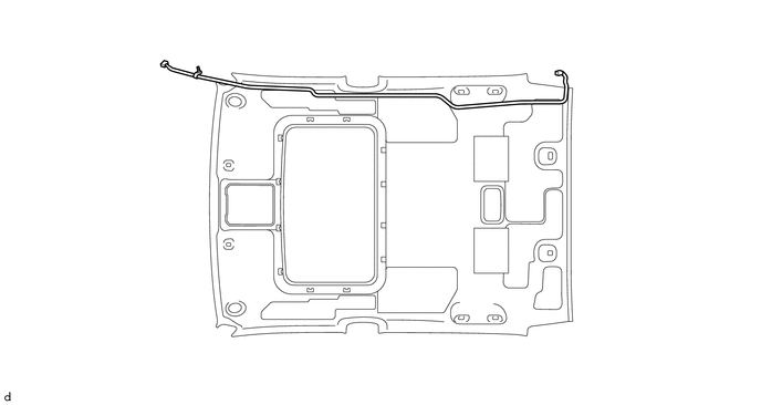
6. REMOVE NO. 2 ANTENNA CORD SUB-ASSEMBLY (w/o Sliding Roof)
(a) Remove the No. 2 antenna cord sub-assembly.
 Components
COMPONENTS
ILLUSTRATION
*A
w/o Woofer
*B
w/ Woofer
*1
LUGGAGE COMPARTMENT SIDE TRAY LH
*2
LUGGAGE COMP ...
 Installation
INSTALLATION
PROCEDURE
1. INSTALL ROOF HEADLINING ASSEMBLY
(a) Insert the roof headlining assembly into the vehicle from the front
door RH side.
NOTICE:
Check that ...
Other materials:
Pressure Control Solenoid "B" Circuit Open (P077513)
DESCRIPTION
Changing from 1st to 6th is performed by the ECM turning shift solenoid valves
SL1, SL2, SL3 and SL4 on and off. If an open or short circuit occurs in any of the
shift solenoid valves, the ECM controls the remaining normal shift solenoid valves
to allow the vehicle to be operated ...
Terminals Of Ecu
TERMINALS OF ECU
1. CHECK DRIVER SIDE JUNCTION BLOCK AND MAIN BODY ECU (MULTIPLEX NETWORK BODY
ECU)
(a) Disconnect the MB main body ECU (multiplex network body ECU) connectors.
(b) Measure the voltage and resistance according to the value(s) in the table
below.
HINT:
Measure the values on ...
Air Conditioning Amplifier Communication Stop Mode
DESCRIPTION
Detection Item
Symptom
Trouble Area
Air Conditioning Amplifier Communication Stop Mode
Either condition is met:
Communication stop for "Air Conditioning Amplifier" is indicated
on the "Commun ...
