Toyota Tacoma (2015-2018) Service Manual: Fuel Sender Gauge Assembly
Components
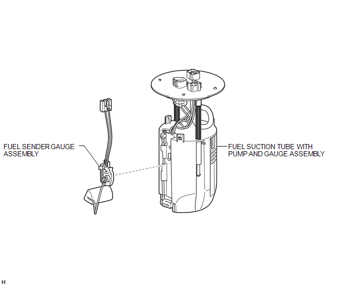
COMPONENTS
ILLUSTRATION
Inspection
INSPECTION
PROCEDURE
1. INSPECT FUEL SENDER GAUGE ASSEMBLY
|
(a) Check that the float moves smoothly between F and E. Text in Illustration
|
|
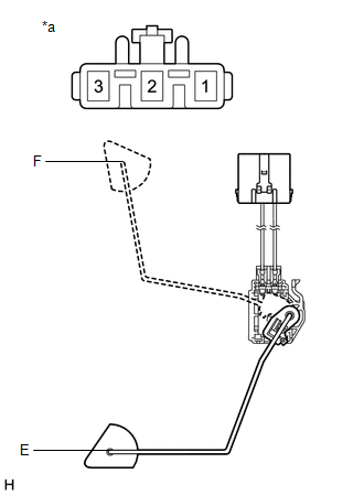
(b) Measure the resistance according to the value(s) in the table below.
Standard Resistance:
|
Tester Connection |
Condition |
Specified Condition |
|---|---|---|
|
2 - 3 |
Float position is F (upper) |
13.5 to 16.5 Ω |
|
Float position is E (lower) |
405.5 to 414.5 Ω |
If the result is not as specified, replace the fuel sender gauge assembly.
Removal
REMOVAL
PROCEDURE
1. REMOVE FUEL SUCTION TUBE WITH PUMP AND GAUGE ASSEMBLY
(See page .gif) )
)
2. REMOVE FUEL SENDER GAUGE ASSEMBLY
|
(a) Disconnect the fuel sender gauge assembly connector. |
|
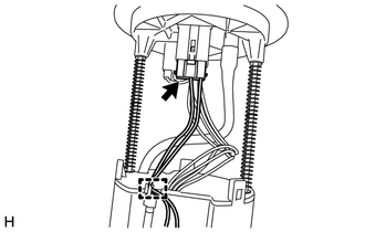
(b) Disengage the clamp and disconnect the wire harness.
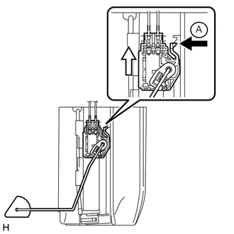
(c) Press down on the fuel sender gauge claw labeled A. Then slide the fuel sender gauge assembly upward to remove it.
 Text in Illustration
.png) |
Press down |
.png) |
Slide |
Installation
INSTALLATION
PROCEDURE
1. INSTALL FUEL SENDER GAUGE ASSEMBLY
(a) Set the fuel sender gauge assembly on the No. 1 fuel sub-tank. Then slide the fuel sender gauge assembly downward to install it.
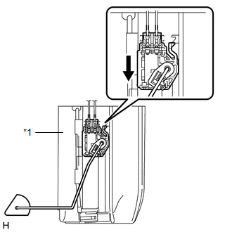 Text in Illustration
|
*1 |
No. 1 Fuel Sub-Tank |
.png) |
Slide |
(b) Engage the clamp and connect the wire harness.
(c) Connect the fuel sender gauge assembly connector.
2. INSTALL FUEL SUCTION TUBE WITH PUMP AND GAUGE ASSEMBLY
(See page .gif) )
)
 Installation
INSTALLATION
CAUTION / NOTICE / HINT
HINT:
Perform "Inspection After Repairs" after replacing the fuel pump assembly (See
page ).
PROCEDURE
1. SET FUEL PUMP ASSEMBLY
HINT:
Perform ...
 Fuel System
...
Other materials:
TC and CG Terminal Circuit
DESCRIPTION
Connecting terminals TC and CG of the DLC3 causes the ECU to display the DTC
by blinking the ABS warning light and slip indicator light.
WIRING DIAGRAM
CAUTION / NOTICE / HINT
NOTICE:
When replacing the skid control ECU (brake actuator assembly), perform zero point
calibration ...
Installation
INSTALLATION
CAUTION / NOTICE / HINT
HINT:
Use the same procedures for both the LH and RH sides.
The procedure described below is for the LH side.
PROCEDURE
1. INSTALL OUTER REAR VIEW MIRROR ASSEMBLY
(a) Engage the claw to install the outer rear view mirror assembly.
(b) Ins ...
Removal
REMOVAL
PROCEDURE
1. TABLE OF BOLT, SCREW AND NUT
HINT:
All bolts, screws and nuts relevant to installing and removing the instrument
panel are shown along with their alphabetic codes in the table below.
2. PRECAUTION
NOTICE:
After turning the ignition switch off, waiting time may be requ ...
