Toyota Tacoma (2015-2018) Service Manual: Installation
INSTALLATION
PROCEDURE
1. INSTALL ROOF HEADLINING ASSEMBLY
|
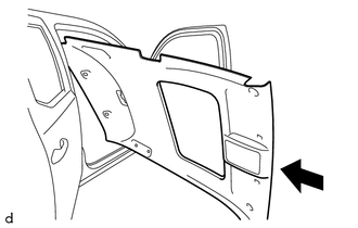
(a) Insert the roof headlining assembly into the vehicle from the front door RH side. NOTICE:
|
|
(b) w/ Sliding Roof:
(1) Engage the 12 fasteners to install the roof headlining.
(2) Connect the connector.
(c) w/o Sliding Roof:
(1) Install the roof headlining.
(2) Engage the clamp.
(d) w/ EC Mirror:
(1) Connect the connector.
(e) w/ Toyota Safety Sense P:
(1) Connect the 2 connectors.
(f) for Rear pillar RH side:
(1) Connect the connector.
(2) Engage the clamp.
(g) for Front pillar LH side:
(1) w/ Toyota Safety Sense P:
- Connect the 2 connectors.
- Engage the clamp and guide.
(2) w/o Toyota Safety Sense P:
- Connect the connector.
- Engage the clamp and guide.
(h) for Front pillar RH side:
(1) Connect the connector.
(2) Engage the clamp.
(3) Engage the guide and install the bolt.
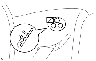
2. INSTALL NO. 1 FORWARD RECOGNITION COVER (w/ Toyota Safety Sense P)
Click here .gif)
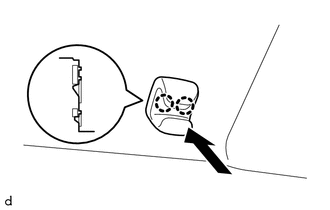
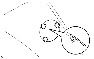
3. INSTALL COAT HOOK
HINT:
Use the same procedure as for the opposite side.
(a) Engage the clip to install the coat hook.
|
(b) Engage the 2 claws to install the cover. |
|
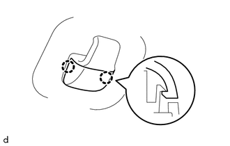
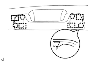
4. INSTALL VISOR HOLDER LH
|
(a) Engage the 2 claws to install the visor holder LH as shown in the illustration. |
|
5. INSTALL VISOR HOLDER RH
HINT:
Use the same procedure as for the LH side.
6. INSTALL VISOR ASSEMBLY LH (w/ Vanity Light)
Click here
7. INSTALL VISOR ASSEMBLY RH (w/ Vanity Light)
HINT:
Use the same procedure as for the LH side.
8. INSTALL VISOR ASSEMBLY LH (w/o Vanity Light)
(a) Engage the guide.
(b) Install the visor assembly LH with the 2 screws.
9. INSTALL VISOR ASSEMBLY RH (w/o Vanity Light)
HINT:
Use the same procedure as for the LH side.
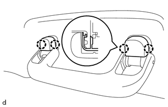
10. INSTALL ASSIST GRIP SUB-ASSEMBLY
HINT:
Use the same procedures as for the opposite side.
(a) Engage the 2 clips to install the assist grip sub-assembly.
|
(b) Engage the 4 claws to install the 2 assist grip covers. |
|
11. INSTALL ROOF CONSOLE BOX ASSEMBLY
Click here
12. INSTALL NO. 1 ROOM LIGHT ASSEMBLY
Click here
13. INSTALL INNER REAR VIEW MIRROR COVER (w/ EC Mirror)
Click here
14. INSTALL QUARTER TRIM INSIDE BOARD LH
(a) Through the rear seat 3 point type outer belt assembly LH to the quarter trim inside board LH.
(b) Engage the 3 clips to install the quarter trim inside board LH.
(c) Install the bolt.
|
(d) Engage the guide and 3 claws to close the cover. |
|
15. INSTALL QUARTER TRIM INSIDE BOARD RH
HINT:
Use the same procedure as for the LH side.
16. CONNECT REAR SEAT 3 POINT TYPE OUTER BELT ASSEMBLY LH
(a) Connect the rear seat 3 point type outer belt assembly LH with the bolt.
Torque:
42 N·m {428 kgf·cm, 31 ft·lbf}
17. CONNECT REAR SEAT 3 POINT TYPE OUTER BELT ASSEMBLY RH
HINT:
Use the same procedure as for the LH side.
18. INSTALL QUARTER TRIM LOWER PANEL LH
(a) Engage the 4 clips and 2 claws to install the quarter trim lower panel LH.
19. INSTALL QUARTER TRIM LOWER PANEL RH
HINT:
Use the same procedure as for the LH side.
20. INSTALL LUGGAGE COMPARTMENT SIDE TRAY RH (w/ Woofer)
(a) Engage the 7 clips and 4 claws to install the luggage compartment side tray RH.
(b) Install the bolt.
21. INSTALL LUGGAGE COMPARTMENT SIDE TRAY RH (w/o Woofer)
(a) Engage the 5 clips and 4 claws to install the luggage compartment side tray RH.
(b) Install the 3 bolts.
22. INSTALL LUGGAGE COMPARTMENT SIDE TRAY LH
(a) Engage the guide, 3 clips and 8 claws to install the luggage compartment side tray LH.
(b) Install the 3 bolts.
23. INSTALL CENTER PILLAR UPPER GARNISH LH
(a) Through the front seat outer belt assembly LH.
(b) Engage the 2 clips to install the center pillar upper garnish LH.
(c) Install the screw.
24. INSTALL CENTER PILLAR UPPER GARNISH RH
HINT:
Use the same procedure as for the LH side.
25. INSTALL CENTER PILLAR LOWER GARNISH LH
(a) Engage the 5 clips and 4 claws to install the center pillar lower garnish LH.
26. INSTALL CENTER PILLAR LOWER GARNISH RH
HINT:
Use the same procedure as for the LH side.
27. CONNECT FRONT SEAT OUTER BELT ASSEMBLY LH
(a) Connect the front seat outer belt assembly LH with the bolt.
Torque:
42 N·m {428 kgf·cm, 31 ft·lbf}
28. CONNECT FRONT SEAT OUTER BELT ASSEMBLY RH
HINT:
Use the same procedure as for the LH side.
29. INSTALL LAP BELT OUTER ANCHOR COVER
HINT:
Use the same procedures as for the opposite side.
(a) Engage the guide and 2 claws to install the lap belt outer anchor cover.
30. INSTALL FRONT PILLAR GARNISH LH
(a) Remove the protector.
(b) Engage the 2 guides and clip to install the front pillar garnish LH.
(c) Install the bolt.
|
(d) Engage the 3 claws to close the cover. |
|
31. INSTALL FRONT PILLAR GARNISH RH
(a) Remove the protector.
(b) Engage the 3 guides to install the front pillar garnish RH.
32. INSTALL ASSIST GRIP SUB-ASSEMBLY
(a) Engage the 2 claws to install the assist grip sub-assembly.
(b) Install the 2 bolts.
|
(c) Engage the 2 guides and 2 claws to close the 2 covers. |
|
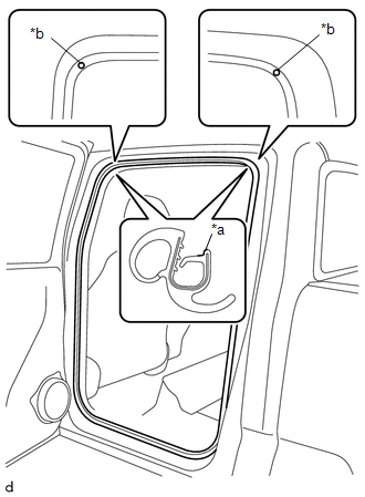
33. INSTALL REAR DOOR OPENING TRIM WEATHERSTRIP LH
|
(a) Align the paint mark on the rear door opening trim weatherstrip LH with the mark position on the vehicle and install the rear door opening trim weatherstrip LH as shown in the illustration. Text in Illustration
Paint Mark:
NOTICE:
HINT: To easily install the weatherstrip, first install the area with the paint mark as shown in the illustration. Then install the part to ward the corners and push any excess length into the corners. |
|
34. INSTALL REAR DOOR OPENING TRIM WEATHERSTRIP RH
HINT:
Use the same procedure as for the LH side.
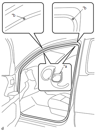
35. INSTALL FRONT DOOR OPENING TRIM WEATHERSTRIP LH
|
(a) Align the paint mark on the front door opening trim weatherstrip LH with the mark position on the vehicle and install the front door opening trim weatherstrip LH as shown in the illustration. Text in Illustration
Paint Mark:
NOTICE:
HINT: To easily install the weatherstrip, first install the area with the paint mark as shown in the illustration. Then install the part to ward the corners and push any excess length into the corners. |
|
36. INSTALL FRONT DOOR OPENING TRIM WEATHERSTRIP RH
HINT:
Use the same procedure as for the LH side.
37. INSTALL REAR DOOR SCUFF PLATE LH
(a) Engage the guide and 9 claws to install the rear door scuff plate LH.
38. INSTALL REAR DOOR SCUFF PLATE RH
HINT:
Use the same procedure as for the LH side.
39. INSTALL COWL SIDE TRIM BOARD LH
(a) Engage the guide and 2 clips to install the cowl side trim board LH.
(b) Install the clip.
40. INSTALL COWL SIDE TRIM BOARD RH
HINT:
Use the same procedure as for the LH side.
41. INSTALL FRONT DOOR SCUFF PLATE LH
(a) Engage the 2 guides and 10 claws to install the front door scuff plate LH.
42. INSTALL FRONT DOOR SCUFF PLATE RH
HINT:
Use the same procedure as for the LH side.
43. INSTALL FRONT CONSOLE BOX
Click here
44. INSTALL REAR SEAT ASSEMBLY LH
Click here
45. INSTALL REAR SEAT ASSEMBLY RH
Click here
46. INSTALL FRONT SEAT ASSEMBLY LH
Click here
47. INSTALL FRONT SEAT ASSEMBLY RH
Click here
 Disassembly
DISASSEMBLY
PROCEDURE
1. REMOVE TELEPHONE MICROPHONE ASSEMBLY
Click here
2. REMOVE MICROPHONE CASE
(a) w/o Sliding Roof:
(1) Disengage the claw and guide to remove the microphone ...
 Interior Panel
...
Other materials:
Problem Symptoms Table
PROBLEM SYMPTOMS TABLE
NOTICE:
When replacing the skid control ECU (brake actuator assembly), sensor, etc.,
turn the ignition switch off.
HINT:
Use the table below to help determine the cause of problem symptoms.
If multiple suspected areas are listed, the potential causes of the s ...
Short in Front Passenger Side Knee Airbag Squib Circuit (B1865/65-B1868/65)
DESCRIPTION
The passenger side knee airbag squib circuit consists of the airbag sensor assembly
and lower No. 2 instrument panel airbag assembly.
The airbag sensor assembly uses this circuit to deploy the airbag when deployment
conditions are met. These DTCs are stored when a malfunction is de ...
Problem Symptoms Table
PROBLEM SYMPTOMS TABLE
HINT:
Use the table below to help determine the cause of problem symptoms. If multiple
suspected areas are listed, the potential causes of the symptoms are listed in order
of probability in the "Suspected Area" column of the table. Check each symptom by
check ...
