Toyota Tacoma (2015-2018) Service Manual: Disassembly
DISASSEMBLY
PROCEDURE
1. REMOVE REAR BUMPER HOLE COVER
|
(a) Disengage the 2 clips to remove the rear bumper hole cover. |
|
2. REMOVE REAR BUMPER PAD SUB-ASSEMBLY
|
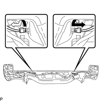
(a) Separate the 2 license plate light assemblies as shown in the illustration. |
|
|
(b) Disconnect the connector to remove the license plate light socket. HINT: Use the same procedure for the RH side and LH side. |
|
.png)
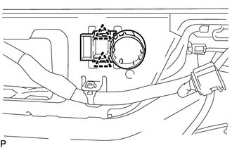
(c) w/ Clearance Sonar System:
(1) Remove the 3 clips.
.png)
(2) Disengage the 14 claws to separate the rear bumper pad sub-assembly.
(3) Disconnect the 2 connectors to remove the rear bumper pad sub-assembly.
(d) w/o Clearance Sonar System:
(1) Remove the 3 clips.
.png)
(2) Disengage the 14 claws to remove the rear bumper pad sub-assembly.
|
(e) Disengage the 2 claws to remove the license plate light lens. HINT: Use the same procedure for the RH side and LH side. |
|
.png)
3. REMOVE NO. 1 ULTRASONIC SENSOR (w/ Clearance Sonar System)
.gif)
4. REMOVE REAR BUMPER PLATE
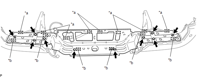
(a) Disengage the wire harness clamps.
 Text in Illustration
|
*a |
Wire Harness Clamp |
*b |
Guide |
(b) Remove the 10 bolts.
(c) Disengage the 6 guides to remove the rear bumper plate.
5. REMOVE REAR BUMPER EXTENSION LH
|
(a) Remove the 5 clips. Text in Illustration
|
|
.png)
(b) Remove the clamp.
(c) w/ Clearance Sonar System:
(1) Disconnect the connector.
(d) Remove the rear bumper extension LH.
6. REMOVE REAR BUMPER EXTENSION RH
HINT:
Use the same procedure as for the LH side.
7. REMOVE NO. 1 ULTRASONIC SENSOR (w/ Clearance Sonar System)
8. REMOVE BLIND SPOT MONITOR SENSOR LH (w/ Blind Spot Monitor)
|
(a) Disconnect the connector. |
|
.png)
(b) Remove the 3 nuts and blind spot monitor sensor LH.
9. REMOVE BLIND SPOT MONITOR SENSOR RH (w/ Blind Spot Monitor)
HINT:
Use the same procedure as for the LH side.
10. REMOVE NO. 6 FLOOR WIRE
|
(a) Remove the 2 adhesive tapes. Text in Illustration
|
|
.png)
(b) Disengage the wire harness clamps to remove the No. 6 floor wire.
11. REMOVE REAR BUMPER SIDE STAY LH
|
(a) Remove the 2 bolts and rear bumper side stay LH. |
|
.png)
12. REMOVE REAR BUMPER SIDE STAY RH
HINT:
Use the same procedure as for the LH side.
 Removal
REMOVAL
CAUTION / NOTICE / HINT
HINT:
If the bumper is damaged, there is a possibility that the installation area of
the blind spot monitor sensor may be deformed and the blind spot monitor syste ...
 Installation
INSTALLATION
PROCEDURE
1. INSTALL REAR BUMPER ASSEMBLY
(a) Using an engine lifter or equivalent, engage the 2 pins to install the rear
bumper assembly.
Text in Illustration
*a
...
Other materials:
Inspection
INSPECTION
PROCEDURE
1. INSPECT MAGNET STARTER SWITCH ASSEMBLY
(a) Inspect the pull-in coil.
(1) Measure the resistance according to the value(s) in the table below.
Text in Illustration
*a
Terminal 50
*b
...
Terminals Of Ecu
TERMINALS OF ECU
1. CHECK DRIVER SIDE JUNCTION BLOCK AND MAIN BODY ECU (MULTIPLEX NETWORK BODY
ECU)
(a) Disconnect the MB main body ECU (multiplex network body ECU) connectors.
(b) Measure the voltage and resistance according to the value(s) in the table
below.
HINT:
Measure the values on ...
Diagnosis System
DIAGNOSIS SYSTEM
1. DESCRIPTION
(a) Blind spot monitor data and Diagnostic Trouble Codes (DTCs) can be read from
the Data Link Connector 3 (DLC3) of the vehicle. When the system seems to be malfunctioning,
use the Techstream to check for malfunctions and to repair it.
2. CHECK DLC3
(a) Check ...
