Toyota Tacoma (2015-2018) Service Manual: Terminals Of Ecu
TERMINALS OF ECU
1. CHECK DRIVER SIDE JUNCTION BLOCK AND MAIN BODY ECU (MULTIPLEX NETWORK BODY ECU)
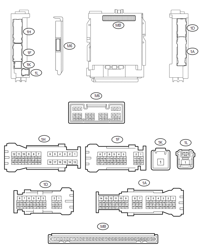
(a) Disconnect the MB main body ECU (multiplex network body ECU) connectors.
(b) Measure the voltage and resistance according to the value(s) in the table below.
HINT:
Measure the values on the wire harness side with the connectors disconnected.
|
Tester Connection |
Wiring Color |
Terminal Description |
Condition |
Specified Condition |
|---|---|---|---|---|
|
MB-11(GND1) - Body ground |
- |
Ground |
Always |
Below 1 Ω |
|
MB-31 (BECU) - Body ground |
- |
Battery power supply |
Always |
11 to 14 V |
|
MB-30 (ACC) - Body ground |
- |
ACC power supply |
Ignition switch ACC |
11 to 14 V |
|
MB-30 (ACC) - Body ground |
- |
ACC power supply |
Ignition switch off |
Below 1 V |
|
MB-32 (IG) - Body ground |
- |
IG power supply |
Ignition switch ON |
11 to 14 V |
|
MB-32 (IG) - Body ground |
- |
IG power supply |
Ignition switch off |
Below 1 V |
If the result is not as specified, there may be a malfunction in the wire harness.
(c) Reconnect the MB main body ECU (multiplex network body ECU) connectors.
(d) Measure the voltage and check for pulses according to the value(s) in the table below.
|
Tester Connection |
Wiring Color |
Terminal Description |
Condition |
Specified Condition |
|---|---|---|---|---|
|
1H-10 (ACT-) - Body ground |
LA-G - Body ground |
Door lock motor unlock drive output (except driver door) |
Door control switch or driver door key cylinder off |
Below 1 V |
|
Door control switch or driver door key cylinder unlocked |
11 to 14 V |
|||
|
1D-3 (ACT-) - Body ground |
G - Body ground |
Door lock motor unlock drive output (except driver door) |
Door control switch or driver door key cylinder off |
Below 1 V |
|
Door control switch or driver door key cylinder unlocked |
11 to 14 V |
|||
|
1D-1 (ACT+) - Body ground |
R - Body ground |
Door lock motor lock drive output (all doors) |
Door control switch or driver door key cylinder off |
Below 1 V |
|
Door control switch or driver door key cylinder locked |
11 to 14 V |
|||
|
1H-12 (ACT+) - Body ground |
LA-R - Body ground |
Door lock motor lock drive output (all doors) |
Door control switch or driver door key cylinder off |
Below 1 V |
|
Door control switch or driver door key cylinder locked |
11 to 14 V |
|||
|
1D-2 (ACTD) - Body ground |
B - Body ground |
Driver door lock motor unlock drive output |
Door control switch or driver door key cylinder off |
Below 1 V |
|
Door control switch or driver door key cylinder unlocked |
11 to 14 V |
|||
|
M6-2 (UL3) - Body ground |
G - Body ground |
Driver door key-linked unlock input |
Driver door key cylinder turned to neutral position → on (unlock) |
Pulse generation → Below 1 V |
|
M6-29 (L2) - Body ground |
SB - Body ground |
Driver door key-linked lock input |
Driver door key cylinder turned to neutral position → on (lock) |
Pulse generation → Below 1 V |
|
M6-27 (FRCY) - Body ground |
LG - Body ground |
Front door courtesy light switch RH input |
Front door RH open |
Below 1 V |
|
M6-27 (FRCY) - Body ground |
LG - Body ground |
Front door courtesy light switch RH input |
Front door RH open |
11 to 14 V |
|
M6-6 (FLCY) - Body ground |
Y - Body ground |
Front door courtesy light switch LH input |
Front door LH open |
Below 1 V |
|
M6-6 (FLCY) - Body ground |
Y - Body ground |
Front door courtesy light switch LH input |
Front door LH closed |
11 to 14 V |
|
1H-36 (LCTY) - Body ground |
P - Body ground |
Rear door courtesy light switch LH input*1 Upper access panel lock assembly LH input*2 Lower access panel lock assembly LH input*2 |
Rear door LH open |
Below 1 V |
|
1H-36 (LCTY) - Body ground |
P - Body ground |
Rear door courtesy light switch LH input*1 Upper access panel lock assembly LH input*2 Lower access panel lock assembly LH input*2 |
Rear door LH closed |
Pulse generation |
|
1D-30 (RCTY) - Body ground |
V - Body ground |
Rear door courtesy light switch RH input*1 Upper access panel lock assembly RH input*2 Lower access panel lock assembly RH input*2 |
Rear door RH open |
Below 1 V |
|
1D-30 (RCTY) - Body ground |
V - Body ground |
Rear door courtesy light switch RH input*1 Upper access panel lock assembly RH input*2 Lower access panel lock assembly RH input*2 |
Rear door RH closed |
Pulse generation |
|
1D-11 (LSFL) - Body ground |
P - Body ground |
Front door LH unlock detection switch input |
Front door LH unlocked |
Below 1 V |
|
1D-11 (LSFL) - Body ground |
P - Body ground |
Front door LH unlock detection switch input |
Ignition switch off, all doors closed and front door LH locked |
Pulse generation |
|
1D-24 (LSFR) - Body ground |
GR - Body ground |
Front door RH unlock detection switch input |
Front door RH unlocked |
Below 1 V |
|
1D-24 (LSFR) - Body ground |
GR - Body ground |
Front door RH unlock detection switch input |
Ignition switch off, all doors closed and front door RH locked |
Pulse generation |
|
1A-41 (LSR) - Body ground |
Y - Body ground |
Rear door RH unlock detection switch input |
Rear door RH or LH unlocked |
Below 1 V |
|
1A-41 (LSR) - Body ground |
Y - Body ground |
Rear door RH unlock detection switch input |
Ignition switch off, all doors closed and rear door RH and LH locked |
Pulse generation |
|
1H-27 (LSR) - Body ground |
L - Body ground |
Rear door LH unlock detection switch input |
Rear door LH or RH unlocked |
Below 1 V |
|
1H-27 (LSR) - Body ground |
L - Body ground |
Rear door LH unlock detection switch input |
Ignition switch off, all doors closed and rear door LH and RH locked |
Pulse generation |
|
1F-29 (BZR) - Body ground |
Y - Body ground |
Wireless door lock buzzer signal |
Wireless door lock buzzer off |
Below 1 V |
|
1F-29 (BZR) - Body ground |
Y - Body ground |
Wireless door lock buzzer signal |
Wireless door lock buzzer on |
Pulse generation |
|
31-1D (KSW) - Body ground*5 |
G - Body ground |
Key unlock warning switch input |
Key in ignition key cylinder |
Below 1 V |
|
No key in ignition key cylinder |
11 to 14 V or Pulse generation |
- *1: for Double Cab
- *2: for Access Cab
- *3: w/ Jam Protection
- *4: w/o Jam Protection
- *5: w/o Smart Key System
 Problem Symptoms Table
PROBLEM SYMPTOMS TABLE
Use the table below to help determine the cause of problem symptoms.
If multiple suspected areas are listed, the potential causes of the symptoms
are listed in o ...
 All Doors LOCK/UNLOCK Functions do not Operate Via Door Control Switch or Door
Key Cylinder
All Doors LOCK/UNLOCK Functions do not Operate Via Door Control Switch or Door
Key Cylinder
DESCRIPTION
The main body ECU (multiplex network body ECU) receives switch signals from the
power window regulator master switch assembly and driver door key cylinder lock
or unlock switch signal ...
Other materials:
Removal
REMOVAL
PROCEDURE
1. REMOVE SPIRAL CABLE WITH SENSOR SUB-ASSEMBLY
(See page )
2. REMOVE WINDSHIELD WIPER SWITCH ASSEMBLY
3. REMOVE HEADLIGHT DIMMER SWITCH ASSEMBLY
(a) Disconnect the connector.
(b) Disengage the 3 claws to remove the he ...
Driving the vehicle
The following procedures should be observed to ensure safe driving.
■ Starting the engine
■ Driving
Automatic transmission
With the brake pedal depressed,
shift the shift lever to D.
Release the parking brake.
Gradually release the brake pedal
and gently depress the acceler ...
Replacement
REPLACEMENT
CAUTION / NOTICE / HINT
NOTICE:
Immediately wash off any brake fluid that comes into contact with any painted
surfaces.
HINT:
If any work is done on the brake system or if air in the brake lines is suspected,
bleed the air from the system.
PROCEDURE
1. FILL RESERVOIR WITH BRAK ...
