Toyota Tacoma (2015-2018) Service Manual: Disassembly
DISASSEMBLY
PROCEDURE
1. REMOVE REAR PROPELLER SHAFT BOOT CLAMP
|
(a) Place matchmarks on the propeller shaft and sleeve yoke. Text in Illustration
|
|
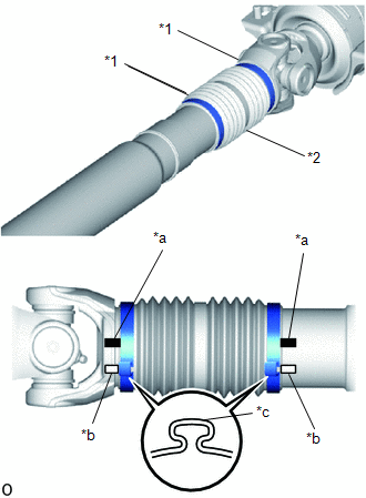
(b) Apply matchmarks at the pinching portions of the rear propeller shaft boot clamps of the propeller shaft and sleeve yoke.
HINT:
- Make sure to place matchmarks to clearly identify the location of the
pinching portions of the propeller shaft boot clamps.
If the pinching portions are installed at different locations than where they were located before disassembly, the rotational balance of the propeller shaft cannot be ensured, which may result in vibrations and noise.
- Make sure that the matchmarks are different enough so that they cannot be confused with each other.
- The locations of the pinching portions may differ from those shown in the illustration, so make sure to confirm and properly place matchmarks in each vehicle.
(c) Using a side cutter or pliers, disconnect the 2 rear propeller shaft boot clamps.
(d) Disconnect the 2 rear propeller shaft boot clamps from the sleeve yoke.
(e) Remove the sleeve yoke, and then remove the rear sliding shaft boot and 2 rear propeller shaft boot clamps from the propeller shaft.
2. INSPECT PROPELLER SHAFT UNIVERSAL JOINT SPIDER BEARING
(a) Check the spider bearings for wear and damage.
(b) Check each spider bearing's axial play by turning the yoke while holding the shaft tightly.
Maximum bearing axial play:
0 to 0.05 mm (0 to 0.00197 in.)
If the bearing axial play is greater than the maximum, replace the spider bearing.
3. REMOVE PROPELLER SHAFT UNIVERSAL JOINT SPIDER BEARING
|
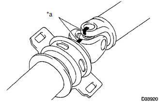
(a) Place matchmarks on the propeller shaft and universal joint yoke. Text in Illustration
|
|
|
(b) Using a brass bar and hammer, slightly tap in the spider bearing outer races. |
|
.png)
(c) Using needle-nose pliers, remove the 4 snap rings from the grooves.
|
(d) Clamp the propeller shaft in a vise between aluminum plates. |
|
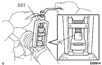
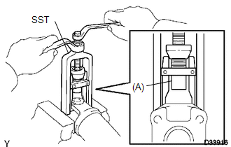
(e) Using SST, push the spider bearing out of the propeller shaft.
SST: 09332-25010
HINT:
Sufficiently raise the part indicated by (A) so that it does not come into contact with the spider bearing.
|
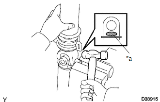
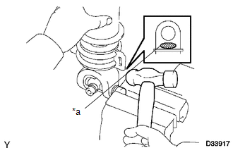
(f) Clamp the pushed out spider bearing outer race in a vise and tap the propeller shaft to remove the spider bearing. Text in Illustration
NOTICE: Do not tap the shaft tube. HINT: Remove the spider bearing from the opposite side of the spider using the same procedure. |
|
(g) Separate the propeller shaft with center bearing assembly.
|
(h) Reinstall the 2 removed spider bearings onto the spider and clamp the spider bearings in a vise. |
|
(i) Using SST, push the bearing out of the yoke.
SST: 09332-25010
HINT:
Sufficiently raise the part indicated by (A) so that it does not come into contact with the bearing.
|
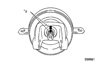
(j) Clamp the pushed out outer bearing race in a vise and tap off the yoke with a hammer. Text in Illustration
|
|
(k) Remove the spider.
4. REMOVE CENTER NO. 2 SUPPORT BEARING ASSEMBLY
|
(a) Fix the yoke at the center bearing section in a vice. Text in Illustration
|
|
(b) Using a chisel and a hammer, loosen the staked part of the lock nut.
(c) Place matchmarks on the yoke and shaft.
(d) Using a brass bar and hammer, remove the center yoke, spacer and center support bearing from the propeller shaft with center bearing assembly.
 Removal
REMOVAL
PROCEDURE
1. REMOVE PROPELLER SHAFT WITH CENTER BEARING ASSEMBLY
(a) Place matchmarks on the propeller shaft flange yoke and differential
flange.
Text in Illustration
...
 Inspection
INSPECTION
PROCEDURE
1. INSPECT PROPELLER SHAFT WITH CENTER BEARING ASSEMBLY
(a) Using a dial indicator, check the propeller shaft runout.
Maximum runout:
0.6 mm (0.0236 in.)
If the shaft run ...
Other materials:
Removal
REMOVAL
PROCEDURE
1. PRECAUTION
NOTICE:
After turning the ignition switch off, waiting time may be required before disconnecting
the cable from the negative (-) battery terminal. Therefore, make sure to read the
disconnecting the cable from the negative (-) battery terminal notices before pr ...
Basic audio operations
Basic audio operations and functions common to each mode are explained in
this section.
Operating the multimedia system
1. Press this button to eject a disc
2. Insert a disc into the disc slot
3.ŌĆ£Select Audio SourceŌĆØ screen appears
4. Turn this knob to select radio station bands, tracks ...
Interior
*1: If equipped
* 2: Access Cab and Double Cab models
*3: Vehicles with auto anti- glare inside rear view mirror
*1: If equipped
*2: Vehicles with an automatic transmission
* : If equipped
* 1: If equipped
* 2: Vehicles with sub woofer ...
