Toyota Tacoma (2015-2018) Service Manual: Removal
REMOVAL
PROCEDURE
1. REMOVE PROPELLER SHAFT WITH CENTER BEARING ASSEMBLY
|
(a) Place matchmarks on the propeller shaft flange yoke and differential flange. Text in Illustration
|
|
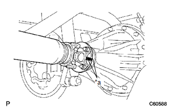
(b) for Differential Type BD20:
(1) Remove the 4 nuts, 4 bolts and 4 washers to disconnect the propeller shaft.
(c) for Differential Type BD22:
(1) Remove the 4 nuts and 4 washers to disconnect the propeller shaft.
|
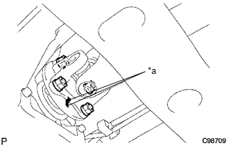
(d) Remove the 2 bolts to separate the center No. 2 support bearing assembly from the frame crossmember. |
|
.png)
|
(e) Place matchmarks on the propeller shaft flange yoke and transfer flange. Text in Illustration
|
|
(f) Remove the 4 nuts, 4 washers and propeller shaft.
 Components
COMPONENTS
ILLUSTRATION
...
 Disassembly
DISASSEMBLY
PROCEDURE
1. REMOVE REAR PROPELLER SHAFT BOOT CLAMP
(a) Place matchmarks on the propeller shaft and sleeve yoke.
Text in Illustration
*1
...
Other materials:
Main Switch Illumination Circuit
DESCRIPTION
When the light control switch is turned to the tail or head position, this circuit
sends an illumination signal to the wireless charger main switch (mobile wireless
charger switch). Based on this signal, the wireless charger main switch (mobile
wireless charger switch) is illumina ...
Transmitter ID1 Operation Stop (C2111/11-C2114/14)
DESCRIPTION
The tire pressure warning valve and transmitters that are installed in the tire
and wheel assemblies measure the tire pressure of each wheel. The measured values
are transmitted to the tire pressure warning ECU and receiver in the vehicle as
radio waves. The ECU compares the measu ...
Theft Deterrent System cannot be Set or Unset
DESCRIPTION
When the ignition switch is turned off and all doors and the engine hood are
closed, the theft deterrent system is set when doors are locked by wireless operation*1,
key linked operation or entry operation*2. If all doors are closed but engine hood
is open when doors are locked by ...
