Toyota Tacoma (2015-2018) Service Manual: Inspection
INSPECTION
PROCEDURE
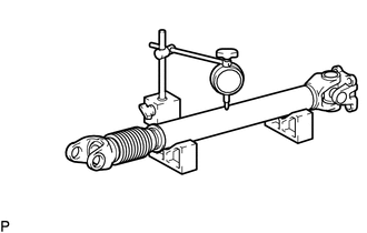
1. INSPECT PROPELLER SHAFT WITH CENTER BEARING ASSEMBLY
(a) Using a dial indicator, check the propeller shaft runout.
Maximum runout:
0.6 mm (0.0236 in.)
If the shaft runout is greater than the maximum, replace the shaft.
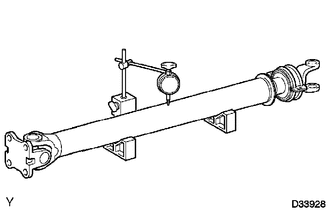
2. INSPECT PROPELLER SHAFT
(a) Using a dial indicator, check the propeller shaft runout.
Maximum runout:
0.6 mm (0.0236 in.)
If the shaft runout is greater than the maximum, replace the shaft.
 Disassembly
DISASSEMBLY
PROCEDURE
1. REMOVE REAR PROPELLER SHAFT BOOT CLAMP
(a) Place matchmarks on the propeller shaft and sleeve yoke.
Text in Illustration
*1
...
 Installation
INSTALLATION
PROCEDURE
1. INSPECT PROPELLER SHAFT WITH CENTER BEARING ASSEMBLY (with Grease Fitting)
Text in Illustration
*1
Grease Fitting
-
-
...
Other materials:
ABS Warning Light Remains ON
DESCRIPTION
The skid control ECU (brake actuator assembly) is connected to the combination
meter assembly via CAN communication.
If any of the following is detected, the ABS warning light remains on:
The skid control ECU (brake actuator assembly) connectors are disconnected
from the ...
Side Turn Signal Light Assembly
Components
COMPONENTS
ILLUSTRATION
Removal
REMOVAL
CAUTION / NOTICE / HINT
HINT:
Use the same procedure for both the RH and LH sides.
The procedure described below is for the LH side.
PROCEDURE
1. REMOVE OUTER REAR VIEW MIRROR ASSEMBLY
(See page )
2. REMOVE OUTER ...
Microphone Circuit between Microphone and Radio Receiver
DESCRIPTION
The radio and display receiver assembly and telephone microphone assembly are
connected to each other using the microphone connection detection signal lines.
Using this circuit, the radio and display receiver assembly sends power to the
telephone microphone assembly, and the teleph ...
