Toyota Tacoma (2015-2018) Service Manual: Removal
REMOVAL
PROCEDURE
1. PRECAUTION
NOTICE:
After turning the ignition switch off, waiting time may be required before disconnecting the cable from the negative (-) battery terminal. Therefore, make sure to read the disconnecting the cable from the negative (-) battery terminal notices before proceeding with work.
Clock here .gif)
2. DISCHARGE FUEL SYSTEM PRESSURE
Click here
3. DISCONNECT CABLE FROM NEGATIVE BATTERY TERMINAL
NOTICE:
When disconnecting the cable, some systems need to be initialized after the cable is reconnected.
Click here
4. REMOVE NO. 2 ENGINE UNDER COVER SUB-ASSEMBLY (w/ Off Road Package)
5. REMOVE NO. 1 ENGINE UNDER COVER SUB-ASSEMBLY
6. DRAIN ENGINE COOLANT
Click here
7. REMOVE V-BANK COVER SUB-ASSEMBLY
|
(a) Raise the front of the V-bank cover to disengage the 2 pins. Text in Illustration
|
|
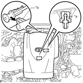
(b) Disengage the 2 guides to remove the V-bank cover sub-assembly.
8. REMOVE NO. 1 V-BANK COVER BRACKET
|
(a) Remove the 2 bolts and No. 1 V-bank cover bracket from the intake air surge tank assembly. |
|
9. REMOVE AIR CLEANER CAP SUB-ASSEMBLY WITH NO. 1 AIR CLEANER HOSE
Click here
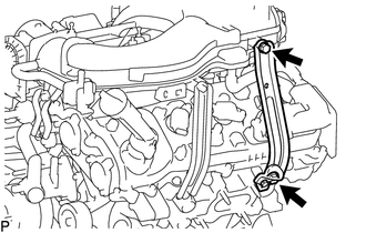
10. REMOVE NO. 2 SURGE TANK STAY
|
(a) Remove the 2 bolts and No. 2 surge tank stay from the cylinder head LH and intake air surge tank assembly. |
|
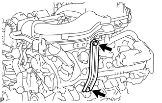
11. REMOVE NO. 1 SURGE TANK STAY
|
(a) Remove the 2 bolts and No. 1 surge tank stay from the cylinder head LH and intake air surge tank assembly. |
|
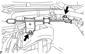
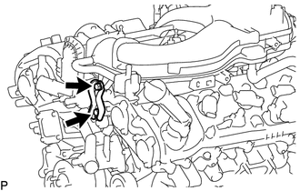
12. REMOVE THROTTLE BODY BRACKET
|
(a) Remove the 2 bolts and throttle body bracket from the timing chain cover assembly and intake air surge tank assembly. |
|
13. REMOVE INTAKE AIR SURGE TANK ASSEMBLY
|
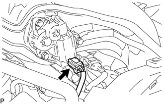
(a) Disconnect the throttle body with motor connector from the throttle body with motor assembly. |
|
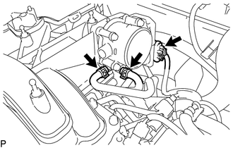
(b) Slide the 2 clips and disconnect the No. 4 water by-pass hose and No. 5 water by-pass hose from the throttle body with motor assembly.
|
(c) Slide the clip and disconnect the fuel vapor feed hose from the purge VSV. |
|
(d) Disengage the clamp to separate the fuel vapor feed hose from the intake air surge tank assembly.
(e) Disconnect the purge VSV connector from the purge VSV.
(f) Disengage the 2 clamps to separate the wire harness from the intake air surge tank assembly.
|
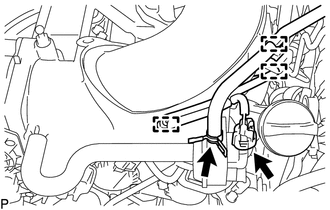
(g) Disengage the clamp to disconnect the No. 1 fuel pipe sub-assembly and No. 2 fuel pipe sub-assembly from the intake air surge tank assembly. |
|
|
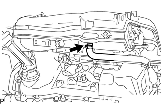
(h) Disengage the clamp to disconnect the heater hose from the intake air surge tank assembly. |
|
.png)
|
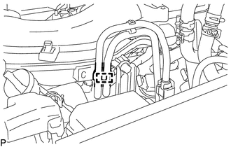
(i) Disconnect the intake air control valve actuator connector from the intake air control valve actuator. |
|
|
(j) Slide the clip and disconnect the PCV hose from the intake air surge tank assembly. |
|
(k) Remove the 2 nuts, 5 bolts and intake air surge tank assembly from the intake manifold.
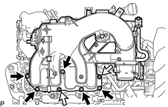 Text in Illustration
.png) |
Bolt |
.png) |
Nut |
(l) Remove the surge tank to intake manifold gasket from the intake air surge tank assembly.
14. DISCONNECT NO. 2 FUEL TUBE SUB-ASSEMBLY
Click here
15. DISCONNECT ENGINE WIRE
Click here
16. REMOVE FUEL DELIVERY PIPE SUB-ASSEMBLY
Click here
17. REMOVE INTAKE MANIFOLD
(a) Remove the 4 nuts, 4 bolts and intake manifold from the cylinder head sub-assembly and cylinder head LH.
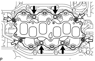 Text in Illustration
|
|
Bolt |
|
|
Nut |
|
(b) Remove the 2 No. 1 intake manifold to head gaskets from the cylinder head sub-assembly and cylinder head LH. |
|
.png)
 Installation
INSTALLATION
PROCEDURE
1. INSTALL INTAKE MANIFOLD
(a) Set 2 new No. 1 intake manifold to head gaskets on cylinder head
sub-assembly and cylinder head LH as shown in the illustration. ...
 Intake System
On-vehicle Inspection
ON-VEHICLE INSPECTION
PROCEDURE
1. INSPECT INTAKE SYSTEM
(a) Check that there is no air suction at the points shown in the illustration.
...
Other materials:
Noise Occurs
PROCEDURE
1.
NOISE CONDITION
(a) Check from which direction the noise comes (front left or right, or rear
left or right).
OK:
The location of the noise source can be determined.
NG
GO TO STEP 3
OK
...
Distance Control Switch Circuit
DESCRIPTION
The distance control switch is used to set the distance for vehicle-to-vehicle
distance control mode. The distance control switch is installed in the steering
pad switch assembly. The vehicle-to-vehicle distance set value can be changed by
operating the steering pad switch assembl ...
Installation
INSTALLATION
CAUTION / NOTICE / HINT
CAUTION:
Some of these service operations affect the SRS airbag system. Read the precautionary
notices concerning the SRS airbag system before servicing.
Click here
PROCEDURE
1. INSTALL FRONT SEAT INNER BELT ASSEMBLY
(a) for Driver Side:
(1) Install t ...
