Toyota Tacoma (2015-2018) Service Manual: Diagnosis System
DIAGNOSIS SYSTEM
1. DESCRIPTION
(a) Air conditioning system data and the Diagnostic Trouble Codes (DTCs) can be read through the Data Link Connector 3 (DLC3) of the vehicle. When the system seems to be malfunctioning, use the Techstream to check for malfunctions and perform troubleshooting.
2. CHECK DLC3
(a) Check the DLC3 (See page .gif) ).
).
3. LIST OF OPERATION METHODS
(a) By operating each of the air conditioning control switches as shown in the diagram below, it is possible to enter diagnostic check mode.
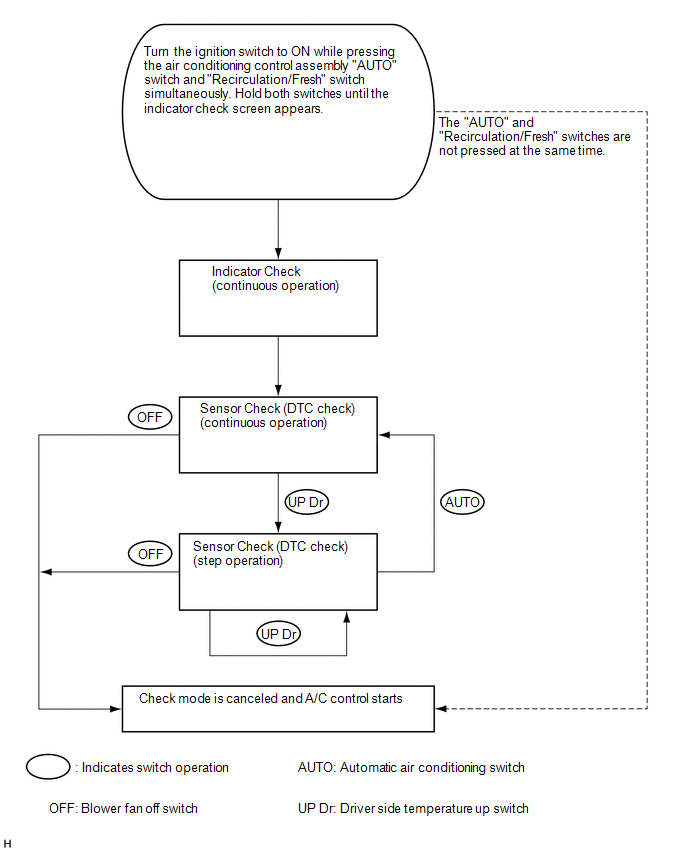
4. INDICATOR CHECK
(a) Turn the ignition switch off.
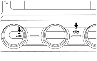
(b) Turn the ignition switch to ON while pressing the air conditioning panel "AUTO" switch and "Recirculation/Fresh" switch simultaneously. Hold both switches until the indicator check screen appears.
 Text in Illustration
|
*a |
Example |
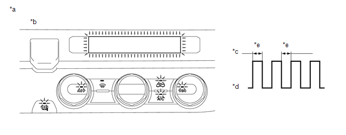
(c) The indicator check is automatically performed when panel diagnosis is activated. Check that the indicators light up and go off 4 times at 1 second intervals continuously.
 Text in Illustration
|
*a |
Example |
*b |
State of indicator check |
|
*c |
On |
*d |
Off |
|
*e |
1 second |
- |
- |
HINT:
- The sensor check automatically starts when the indicator check is completed.
- Press the "OFF" switch to cancel check mode.
5. SENSOR CHECK (DTC CHECK)
(a) Start the engine and warm it up.
(b) Perform the indicator check.
HINT:
After the indicator check is completed, the system enters DTC check mode automatically.
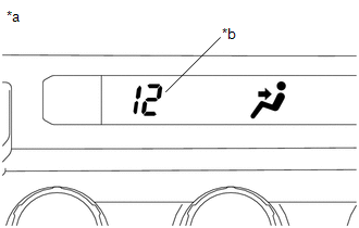
(c) Read the DTCs displayed on the display.
 Text in Illustration
|
*a |
Example |
|
*b |
DTC |
NOTICE:
In sensor check mode, which is automatically entered after indicator check mode, troubleshooting may be partially performed. Be sure to perform the sensor check again.
HINT:
Refer to Diagnostic Trouble Code Chart for details of the codes (See page
).
- When there are no problems, DTC 00 is output.
- As an example, the illustration shows that DTC 12 is output.
(d) If the steps are difficult to read because they change automatically, press the "driver side TEMP UP" switch to display the steps one at a time so that they can be read easily. The items are displayed step by step each time the "driver side TEMP UP" switch is pressed.
HINT:
Press the "OFF" switch to finish panel diagnosis.
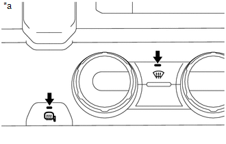
6. SENSOR CHECK (CLEAR DTC)
(a) During the sensor check, press the "Mirror Heater" switch and "Rear DEF" switch simultaneously.
 Text in Illustration
|
*a |
Example |
 System Description
SYSTEM DESCRIPTION
1. GENERAL
(a) The air conditioning system has the following controls.
Control
Outline
Neural Network Control
This control is ca ...
 Problem Symptoms Table
PROBLEM SYMPTOMS TABLE
HINT:
Use the table below to help determine the cause of problem symptoms.
If multiple suspected areas are listed, the potential causes of the symptoms
are lis ...
Other materials:
Power Source Mode does not Change to ON (IG)
DESCRIPTION
If the engine switch is pressed with the electrical key transmitter sub-assembly
in the cabin, the certification ECU (smart key ECU assembly) receives a signal and
changes the power source mode.
HINT:
When the cable is disconnected and reconnected to the negative (-) battery termi ...
Stereo Component Amplifier
Components
COMPONENTS
ILLUSTRATION
ILLUSTRATION
Removal
REMOVAL
PROCEDURE
1. PRECAUTION
NOTICE:
After turning the ignition switch off, waiting time may be required before disconnecting
the cable from the negative (-) battery terminal. Therefore, make sure to read the
disconnecti ...
Multi-terrain Select Switch
Components
COMPONENTS
ILLUSTRATION
Removal
REMOVAL
PROCEDURE
1. REMOVE MULTI-TERRAIN SELECT SWITCH (DRIVE MONITOR SWITCH)
(a) Disengage the 2 claws to remove the multi-terrain select switch (drive
monitor switch).
Inspection ...
