Toyota Tacoma (2015-2018) Service Manual: System Description
SYSTEM DESCRIPTION
1. GENERAL
(a) The air conditioning system has the following controls.
|
Control |
Outline |
|---|---|
|
Neural Network Control |
This control is capable of effecting complex control by artificially simulating the information processing method of the nervous system of living organisms in order to establish a complex input/output relationship that is similar to a human brain. |
|
Outlet Air Temperature Control |
Based on the temperature set at the temperature control switch, the neural network control calculates the outlet air temperature based on the input signals from various sensors. |
|
Left and Right Independent Control |
The temperature setting for the driver and front passenger is controlled independently in order to provide a separate vehicle interior temperature for the right and left side of the vehicle. Thus, air conditioning control that accommodates occupant preferences has been realized. |
|
Blower Control |
Controls the blower motor in accordance with the airflow volume that has been calculated by neural network control based on the input signals from various sensors. |
|
Air Outlet Control |
Automatically switches the air outlets in accordance with the outlet mode that has been calculated by neural network control based on the input signals from various sensors. |
|
In accordance with the engine coolant temperature, ambient air temperature, amount of sunlight, required blower, outlet temperature, and vehicle speed conditions, this control automatically switches the blower outlet to foot and defroster mode to prevent the windows from becoming fogged up when the ambient air temperature is low. |
|
|
Air Inlet Control |
Automatically controls the air inlet control damper to achieve the calculated outlet air temperature that is required. |
|
Drives the air inlet servo motor (damper servo sub-assembly) according to the operation of the air inlet control switch and moves the dampers to the fresh or recirculation position. |
|
|
Automatically moves the damper to the recirculation position to cool the cabin quickly when the air conditioning is auto mode. |
|
|
Compressor Control |
Controls the compressor with magnet clutch assembly to turn on or off based on the signals from various sensors. |
|
Diagnosis |
A Diagnostic Trouble Code (DTC) is stored in the memory when the air conditioner amplifier assembly detects a problem with the air conditioning system. |
2. MODE POSITION AND DAMPER OPERATION
(a) Mode Position and Damper Operation
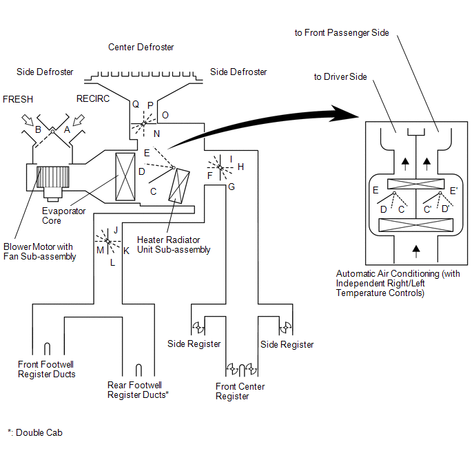 Functions of Main Dampers
|
Control Door |
Operation Position |
Door Position |
Operation |
|
|---|---|---|---|---|
|
Air Inlet Control Door |
FRESH |
A |
Brings in fresh air. |
|
|
RECIRCULATION |
B |
Recirculates internal air. |
||
|
Air Mix Control Door |
MAX COLD to MAX HOT Temperature Setting |
C - D - E (C' - D' - E') |
Varies the mixture ratio of warm air and cool air in order to regulate the temperature continuously between hot and cold. |
|
|
Mode Control Door |
 |
FACE |
F, J, N |
Air blows out of the front center register and side register. |
 |
BI-LEVEL |
G, L, N |
Air blows out of the front center register, side register and front and rear footwell register ducts*. |
|
 |
FOOT |
H, M, O |
Air blows out of the front and rear footwell register ducts*. In addition, air blows out slightly from the front and rear center register*, side register and defroster. |
|
 |
FOOT AND DEFROSTER |
H, M, P |
Defrosts the windshield through the center defroster, side defroster, side register, front and rear center register ducts*, while air is also blown out from the front and rear footwell register ducts*. |
|
 |
DEFROSTER |
I, J, Q |
Defrosts the windshield through the center defroster, side defroster. |
|
- *: for Double Cab
3. AIR OUTLETS AND AIRFLOW VOLUME
(a) Air Outlets and Airflow Volume
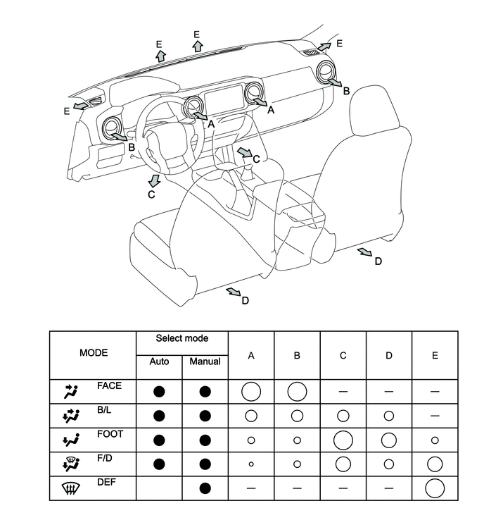
HINT:
The size of each circle â—‹ indicates the ratio of airflow volume.
 How To Proceed With Troubleshooting
CAUTION / NOTICE / HINT
HINT:
Use the following procedure to troubleshoot the air conditioning system.
*: Use the Techstream.
PROCEDURE
1.
VEHICLE BROUG ...
 Diagnosis System
DIAGNOSIS SYSTEM
1. DESCRIPTION
(a) Air conditioning system data and the Diagnostic Trouble Codes (DTCs) can
be read through the Data Link Connector 3 (DLC3) of the vehicle. When the system
seem ...
Other materials:
Cruise Control Switch Circuit
DESCRIPTION
The cruise control main switch is used to turn the dynamic radar cruise control
system on and off, as well as operate 7 functions: SET, - (COAST), TAP-DOWN, RES
(RESUME), + (ACCEL), TAP-UP and CANCEL.
The SET, TAP-DOWN and - (COAST) functions, and the RES (RESUME), TAP-UP and +
( ...
On-vehicle Inspection
ON-VEHICLE INSPECTION
PROCEDURE
1. INSPECT GARAGE DOOR OPENER
(a) Press each switch and check that the red LED turns on. If one or
more of the switches does not turn on the LED, confirm normal operation
of the fuse and wire harness. If the fuse and wire harness are malfunctioni ...
Trailer Socket
Components
COMPONENTS
ILLUSTRATION
Removal
REMOVAL
PROCEDURE
1. REMOVE TRAILER SOCKET
(a) Disconnect the connector.
(b) Disengage the 2 clips to remove the trailer socket.
Install ...
