Toyota Tacoma (2015-2018) Service Manual: Front Stabilizer Bar
Components
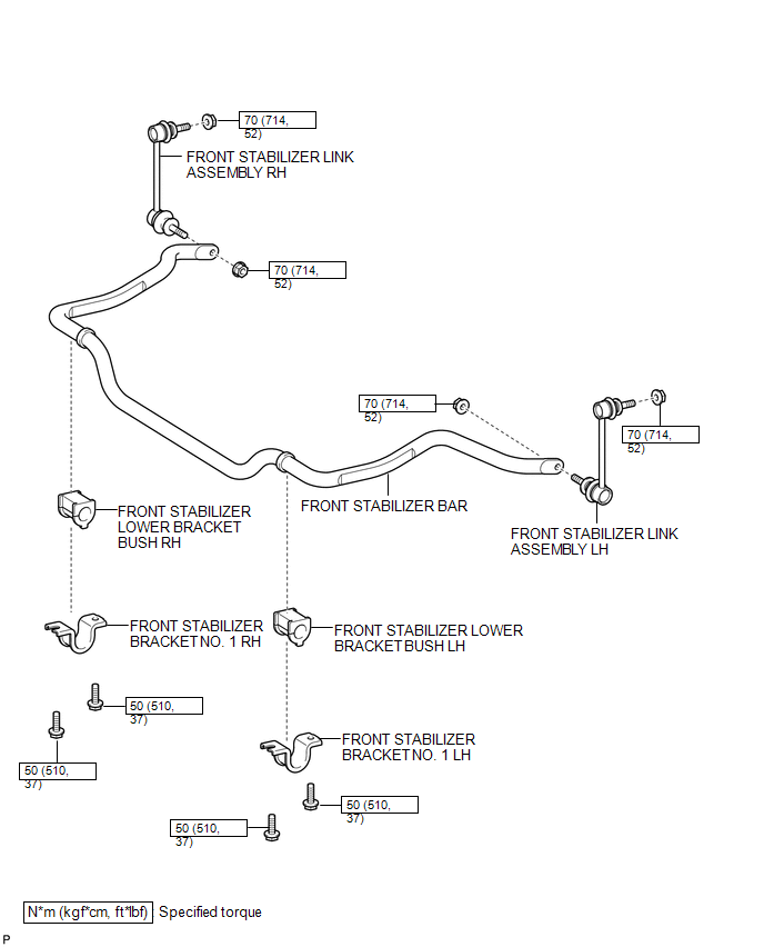
COMPONENTS
ILLUSTRATION
Inspection
INSPECTION
PROCEDURE
1. INSPECT FRONT STABILIZER LINK ASSEMBLY
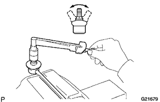
(a) Flip the ball joint stud back and forth 5 times, as shown in the illustration, before installing the nut.
(b) Using a torque wrench, turn the nut continuously at a rate of 2 to 4 seconds per turn and take the torque reading on the 5th turn.
Torque:
0.1-1.9 N·m {1-19 kgf·cm, 1-17 in·lbf}
or less
(c) Check for any cracks and grease leakage on the ball joint dust cover.
Installation
INSTALLATION
PROCEDURE
1. INSTALL FRONT STABILIZER BAR
2. INSTALL FRONT STABILIZER LOWER BRACKET BUSH LH
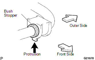
(a) Install the front stabilizer lower bracket bush.
HINT:
- Install the bush onto the inner side of the bush stopper on the stabilizer bar.
- Install the bush as the protrusion to be on the inner side of the vehicle.
3. INSTALL FRONT STABILIZER LOWER BRACKET BUSH RH
HINT:
The installation procedure for the RH side is the same as that for the LH side.
4. INSTALL FRONT STABILIZER BRACKET NO. 1 LH
(a) Install the front stabilizer bracket with the 2 bolts.
Torque:
50 N·m {510 kgf·cm, 37 ft·lbf}
5. INSTALL FRONT STABILIZER BRACKET NO. 1 RH
NOTICE:
The installation procedure for the RH side is the same as that for the LH side.
6. INSTALL FRONT STABILIZER LINK ASSEMBLY LH
(a) Install the front stabilizer link assembly LH with the 2 nuts.
Torque:
70 N·m {714 kgf·cm, 52 ft·lbf}
HINT:
If the ball joint turns together with the nut, use a hexagon (6 mm) wrench to hold the stud.
7. INSTALL FRONT STABILIZER LINK ASSEMBLY RH
HINT:
The installation procedure for the RH side is the same as that for the LH side.
8. INSTALL ENGINE UNDER COVER SUB-ASSEMBLY NO. 1
Torque:
30 N·m {306 kgf·cm, 22 ft·lbf}
9. INSTALL FRONT WHEELS
Torque:
113 N·m {1152 kgf·cm, 83 ft·lbf}
Removal
REMOVAL
PROCEDURE
1. REMOVE FRONT WHEELS
2. REMOVE ENGINE UNDER COVER SUB-ASSEMBLY NO. 1
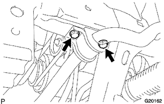
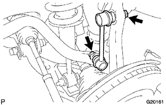
3. REMOVE FRONT STABILIZER LINK ASSEMBLY LH
.png)
(a) Remove the 2 nuts and front stabilizer link LH.
HINT:
If the ball joint turns together with the nut, use a hexagon (6 mm) wrench to hold the stud.
4. REMOVE FRONT STABILIZER LINK ASSEMBLY RH
HINT:
The removal procedure for the RH side is the same as that for the LH side.
5. REMOVE FRONT STABILIZER BRACKET NO. 1 LH
.png)
(a) Remove the 2 bolts and front stabilizer bracket.
6. REMOVE FRONT STABILIZER BRACKET NO. 1 RH
HINT:
The removal procedure for the RH side is the same as that for the LH side.
7. REMOVE FRONT STABILIZER LOWER BRACKET BUSH LH
8. REMOVE FRONT STABILIZER LOWER BRACKET BUSH RH
9. REMOVE FRONT STABILIZER BAR
 Installation
INSTALLATION
CAUTION / NOTICE / HINT
HINT:
Use the same procedure for the RH side and LH side.
The procedure listed below is for the LH side.
PROCEDURE
1. INSTALL FRONT COIL SPR ...
 Front Upper Suspension Arm
Components
COMPONENTS
ILLUSTRATION
Disassembly
DISASSEMBLY
PROCEDURE
1. REMOVE FRONT SUSPENSION UPPER ARM BUSH
(a) Using a hammer and chisel, raise the flange of the bushing diagonally ...
Other materials:
Ambient Temperature Sensor
Components
COMPONENTS
ILLUSTRATION
Inspection
INSPECTION
PROCEDURE
1. INSPECT AMBIENT TEMPERATURE SENSOR
(a) Measure the resistance according to the value(s) in the table below.
Standard resistance:
Tester Connection
Condition
...
Components
COMPONENTS
ILLUSTRATION
HINT:
The following specifications are for BD22AN (w/ Differential Lock). BD22AN differentials
are equipped with M10 rear differential carrier to rear axel housing fasteners.
ILLUSTRATION
ILLUSTRATION
...
Freeze Frame Data
FREEZE FRAME DATA
1. FREEZE FRAME DATA
(a) Whenever a meter DTC is detected, the combination meter assembly stores the
current vehicle state as freeze frame data.
2. CHECK FREEZE FRAME DATA
(a) Connect the Techstream to the DLC3.
(b) Turn the ignition switch to ON.
(c) Turn the Techstream on ...
