Toyota Tacoma (2015-2018) Service Manual: Diagnosis System
DIAGNOSIS SYSTEM
1. DESCRIPTION
(a) To check DTCs, connect the Techstream to the Data Link Connector 3 (DLC3)
of the vehicle. The Techstream displays DTCs and freeze frame data. The DTCs and
freeze frame data can be cleared with the Techstream (See page
.gif) ).
).
2. NORMAL MODE AND CHECK MODE
(a) The diagnosis system operates in "normal mode" during normal vehicle use. In normal mode, "2 trip detection logic" is used to ensure accurate detection of malfunctions. "Check mode" is also available to technicians as an option. In check mode, "1 trip detection logic" is used for simulating malfunction symptoms and increasing the system's ability to detect malfunctions, including intermittent malfunctions.
3. 2 TRIP DETECTION LOGIC
(a) When a malfunction is first detected, the malfunction is stored as a pending DTC in the ECM memory (1st trip). If the same malfunction is detected during the next drive cycle, the DTC is stored (2nd trip).
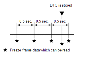
4. FREEZE FRAME DATA
(a) The Techstream records freeze frame data in 5 different instances: 1) 3 times before the DTC is stored, 2) once when the DTC is stored, and 3) once after the DTC is stored. These sets of data can be used to simulate the vehicle condition around the time when the malfunction occurred. The data may help in finding the cause of the malfunction, or in judging if the DTC was caused by a temporary malfunction.
5. CHECK DATA LINK CONNECTOR 3 (DLC3)
(a) Check the DLC3 (See page ).
 Problem Symptoms Table
PROBLEM SYMPTOMS TABLE
Use the table below to help determine the cause of problem symptoms. If multiple
suspected areas are listed, the potential causes of the symptoms are listed in order
of pro ...
 Terminals Of Ecm
TERMINALS OF ECM
HINT:
The standard normal voltage between each pair of ECM terminals is shown in the
table below. The appropriate conditions for checking each pair of terminals are
also indic ...
Other materials:
Terminals Of Ecu
TERMINALS OF ECU
1. CLEARANCE WARNING ECU ASSEMBLY
(a) Disconnect the C30 connector from the clearance warning ECU assembly.
(b) Measure the voltage and resistance according to the value(s) in the table
below.
Terminal No. (Symbol)
Wiring Color
Terminal Descr ...
Fail-safe Chart
FAIL-SAFE CHART
HINT:
If any of the following auto cancel conditions are detected while the dynamic
radar cruise control system is controlling vehicle speed, the system clears the
stored vehicle speed and cancels control of vehicle speed by the dynamic radar cruise
control system.
Automatic ...
Radio Receiver Power Source Circuit
DESCRIPTION
This is the power source circuit to operate the navigation receiver assembly.
WIRING DIAGRAM
CAUTION / NOTICE / HINT
NOTICE:
Inspect the fuses for circuits related to this system before performing
the following inspection procedure.
PROCEDURE
1.
...
