Toyota Tacoma (2015-2018) Service Manual: Terminals Of Ecu
TERMINALS OF ECU
1. CLEARANCE WARNING ECU ASSEMBLY

(a) Disconnect the C30 connector from the clearance warning ECU assembly.
(b) Measure the voltage and resistance according to the value(s) in the table below.
|
Terminal No. (Symbol) |
Wiring Color |
Terminal Description |
Condition |
Specified Condition |
|---|---|---|---|---|
|
C30-9 (CLSW) - C30-30 (E) |
Y - W-B |
Back sonar or clearance sonar switch assembly power source signal |
Ignition switch ON, back sonar or clearance sonar switch assembly on |
11 to 14 V |
|
C30-9 (CLSW) - C30-30 (E) |
Y - W-B |
Back sonar or clearance sonar switch assembly power source signal |
Ignition switch ON, back sonar or clearance sonar switch assembly off |
Below 1 V |
|
C30-1 (IG) - C30-30 (E) |
P - W-B |
IG power source signal |
Ignition switch off |
Below 1 V |
|
Ignition switch ON |
11 to 14 V |
|||
|
C30-30 (E) - Body ground |
W-B - Body ground |
Ground |
Always |
Below 1 Ω |
(c) Reconnect the C30 connector to the clearance warning ECU assembly.
(d) Measure the voltage and check for pulses according to the value(s) in the table below.
|
Terminal No. (Symbol) |
Wiring Color |
Terminal Description |
Condition |
Specified Condition |
|---|---|---|---|---|
|
C30-22 (BOR) - C30-30 (E) |
BE - W-B |
Power source for rear sensor circuit |
Ignition switch off |
Below 1 V |
|
Ignition switch ON, back sonar or clearance sonar switch assembly on |
7.2 to 8.8 V |
|||
|
C30-13 (ER) - C30-30 (E) |
R - W-B |
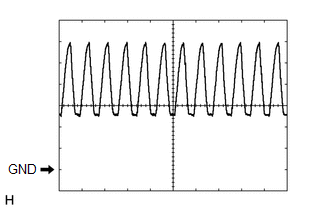
Clearance warning buzzer signal |
Buzzer sounding |
Pulse generation (See waveform 1) |
|
C30-23 (E1) - C30-30 (E) |
B - W-B |
Ground for rear clearance sonar |
Always |
Below 1 V |
|
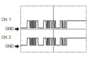
C30-24 (SOR) - C30-30 (E) |
V - W-B |
Rear sensor communication signal (Rear clearance sonar sensor) |
Ignition switch ON, back sonar or clearance sonar switch assembly on, shift lever in R |
Pulse generation (See waveform 2) |
(e) Using an oscilloscope, check waveform 1.
(1) Waveform 1 (Reference)
|
Item |
Content |
|---|---|
|
Terminal No. (Symbol) |
C30-13 (ER) - C30-30 (E) |
|
Tool Setting |
2 V/DIV., 500 ÎĽsec./DIV. |
|
Vehicle Condition |
When sonar detects obstacle (buzzer sounds) |
|
Buzzer volume |
M2 (Medium volume) |
HINT:
The amplitude of the waveform changes according to the set volume.
(f) Using an oscilloscope, check waveform 2.
(1) Waveform 2 (Reference)
|
Item |
Content |
|---|---|
|
Terminal No. (Symbol) |
C30-24 (SOR) - C30-30 (E) |
|
Tool Setting |
5 V/DIV., 1 msec./DIV. |
|
Condition |
Ignition switch ON, back sonar or clearance sonar switch assembly on, shift lever in R |
HINT:
The waveforms for CH1 and CH2 are same.
 Problem Symptoms Table
PROBLEM SYMPTOMS TABLE
HINT:
Use the table below to help determine the cause of problem symptoms.
If multiple suspected areas are listed, the potential causes of the symptoms
are lis ...
 Diagnosis System
DIAGNOSIS SYSTEM
1. DESCRIPTION
(a) When troubleshooting a vehicle with a diagnosis system, the only difference
from the usual troubleshooting procedure is connecting the Techstream to the vehicle ...
Other materials:
Driver Side Door Entry Lock Function does not Operate
DESCRIPTION
If the entry lock function does not operate for the driver door only, but the
entry unlock function operates, the request code is being transmitted properly from
the driver door. In this case, there may be a problem related to the front door
outside handle assembly LH (lock sensor ...
Precaution
PRECAUTION
1. IGNITION SWITCH EXPRESSION
HINT:
The type of ignition switch used on this model differs depending on the specifications
of the vehicle. The expressions listed in the table below are used in this section.
Expression
Ignition Switch (Position)
Engin ...
Side Moulding
Components
COMPONENTS
ILLUSTRATION
ILLUSTRATION
Removal
REMOVAL
CAUTION / NOTICE / HINT
HINT:
Use the same procedure for the RH side and LH side.
The following procedure is for the LH side.
When removing the lower No. 2 side panel moulding, heat the vehicle
body a ...
