Toyota Tacoma (2015-2018) Service Manual: Data Signal Circuit between Radio Receiver and Stereo Jack Adapter
DESCRIPTION
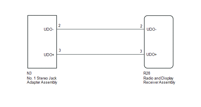
The No. 1 stereo jack adapter assembly sends the sound data signal or image data signal from a USB device to the radio and display receiver assembly via this circuit.
WIRING DIAGRAM
PROCEDURE
|
1. |
CHECK HARNESS AND CONNECTOR (RADIO AND DISPLAY RECEIVER ASSEMBLY - NO. 1 STEREO JACK ADAPTER ASSEMBLY) |
(a) Disconnect the R28 radio and display receiver assembly connector.
(b) Disconnect the N3 No. 1 stereo jack adapter assembly connector.
(c) Measure the resistance according to the value(s) in the table below.
Standard Resistance:
|
Tester Connection |
Condition |
Specified Condition |
|---|---|---|
|
N3-2 (UDO-) - R28-2 (UDO-) |
Always |
Below 1 Ω |
|
N3-3 (UDO+) - R28-3 (UDO+) |
Always |
Below 1 Ω |
|
N3-2 (UDO-) - Body ground |
Always |
10 kΩ or higher |
|
N3-3 (UDO+) - Body ground |
Always |
10 kΩ or higher |
| OK | .gif) |
PROCEED TO NEXT SUSPECTED AREA SHOWN IN PROBLEM SYMPTOMS TABLE |
| NG | |
REPAIR OR REPLACE HARNESS OR CONNECTOR |
 Sound Signal Circuit between Radio Receiver and Stereo Jack Adapter
DESCRIPTION
The No. 1 stereo jack adapter assembly sends the sound signal from an external
device to the radio and display receiver assembly via this circuit.
If there is an open or short in the c ...
 Data Signal Circuit between Radio Receiver and Extension Module
DESCRIPTION
The stereo component tuner assembly sends the image data signal to the radio
and display receiver assembly via this circuit.
WIRING DIAGRAM
PROCEDURE
1.
CHEC ...
Other materials:
How To Proceed With Troubleshooting
CAUTION / NOTICE / HINT
HINT:
Use these procedures to troubleshoot the rear view monitor system.
PROCEDURE
1.
VEHICLE BROUGHT TO WORKSHOP
NEXT
2.
CUSTOMER PROBLEM ANALYSIS
...
Touch Panel Switch does not Function
PROCEDURE
1.
CHECK MULTI-DISPLAY
(a) Check if there is any foreign matter caught between the display and exterior
frame of the multi-display.
OK:
No foreign matter is caught between the display and exterior frame of the multi-display.
HINT:
If there is foreig ...
Removal
REMOVAL
PROCEDURE
1. REMOVE NO. 2 ENGINE UNDER COVER SUB-ASSEMBLY (w/ Off Road Package)
2. REMOVE NO. 1 ENGINE UNDER COVER SUB-ASSEMBLY
3. REMOVE FAN AND GENERATOR V BELT
4. DRAIN POWER STEERING FLUID
5. REMOVE FRONT FENDER APRON UPPER SEAL RH
6. DISCONNECT NO. 1 OIL RESERVOIR TO PUMP ...
