Toyota Tacoma (2015-2018) Service Manual: Sound Signal Circuit between Radio Receiver and Stereo Jack Adapter
DESCRIPTION
The No. 1 stereo jack adapter assembly sends the sound signal from an external device to the radio and display receiver assembly via this circuit.
If there is an open or short in the circuit, sound cannot be heard from the speakers even if there is no malfunction in the radio and display receiver assembly, or speakers.
WIRING DIAGRAM
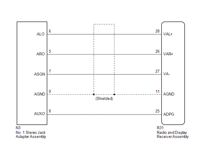
PROCEDURE
|
1. |
CHECK HARNESS AND CONNECTOR (RADIO AND DISPLAY RECEIVER ASSEMBLY - NO. 1 STEREO JACK ADAPTER ASSEMBLY) |
(a) Disconnect the R31 radio and display receiver assembly connector.
(b) Disconnect the N3 No. 1 stereo jack adapter assembly connector.
(c) Measure the resistance according to the value(s) in the table below.
Standard Resistance:
|
Tester Connection |
Condition |
Specified Condition |
|---|---|---|
|
R31-25 (ADPG) - N3-8 (AUXO) |
Always |
Below 1 Ω |
|
R31-26 (VAR+) - N3-5 (ARO) |
Always |
Below 1 Ω |
|
R31-28 (VAL+) - N3-6 (ALO) |
Always |
Below 1 Ω |
|
R31-27 (VA-) - N3-7 (ASGN) |
Always |
Below 1 Ω |
|
R31-11 (AGND) - N3-9 (AGND) |
Always |
Below 1 Ω |
|
R31-25 (ADPG) - Body ground |
Always |
10 kΩ or higher |
|
R31-26 (VAR+) - Body ground |
Always |
10 kΩ or higher |
|
R31-28 (VAL+) - Body ground |
Always |
10 kΩ or higher |
|
R31-27 (VA-) - Body ground |
Always |
10 kΩ or higher |
|
R31-11 (AGND) - Body ground |
Always |
10 kΩ or higher |
| OK | .gif) |
PROCEED TO NEXT SUSPECTED AREA SHOWN IN PROBLEM SYMPTOMS TABLE |
| NG | |
REPAIR OR REPLACE HARNESS OR CONNECTOR |
 Speaker Circuit
DESCRIPTION
If there is a short in a speaker circuit, the radio and display receiver
assembly detects it and stops output to the speakers.
Thus sound cannot be heard from the speakers ...
 Data Signal Circuit between Radio Receiver and Stereo Jack Adapter
DESCRIPTION
The No. 1 stereo jack adapter assembly sends the sound data signal or image data
signal from a USB device to the radio and display receiver assembly via this circuit.
WIRING DIAGRAM
...
Other materials:
Precaution
PRECAUTION
1. PRECAUTIONS WHEN USING TECHSTREAM
(a) When using the Techstream to troubleshoot the engine immobiliser system:
Connect the Techstream to the DLC3 while the ignition switch is off, and turn
a door courtesy light switch on and off at 1.5-second intervals until communication
betwee ...
Freeze Frame Data
FREEZE FRAME DATA
1. FREEZE FRAME DATA
(a) When a DTC is stored, the 4 wheel drive control ECU stores the current vehicle
state as Freeze Frame Data.
HINT:
Freeze Frame Data at the time a DTC is stored:
When the 4 wheel drive control ECU stores data at the time a DTC is stored, no
updates w ...
ECU Power Source Circuit
WIRING DIAGRAM
CAUTION / NOTICE / HINT
NOTICE:
Inspect the fuses for circuits related to this system before performing the following
inspection procedure.
PROCEDURE
1.
INSPECT BATTERY
(a) Check the battery voltage.
Standard voltage:
11 to 14 V
NG
...
