Toyota Tacoma (2015-2018) Service Manual: Removal
REMOVAL
PROCEDURE
1. REMOVE NO. 2 ENGINE UNDER COVER SUB-ASSEMBLY (w/ Off Road Package)
2. REMOVE NO. 1 ENGINE UNDER COVER SUB-ASSEMBLY
3. REMOVE FAN AND GENERATOR V BELT
.gif)
4. DRAIN POWER STEERING FLUID
5. REMOVE FRONT FENDER APRON UPPER SEAL RH
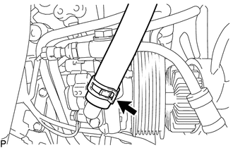
6. DISCONNECT NO. 1 OIL RESERVOIR TO PUMP HOSE
|
(a) Slide the clip and disconnect the No. 1 oil reservoir to pump hose. |
|
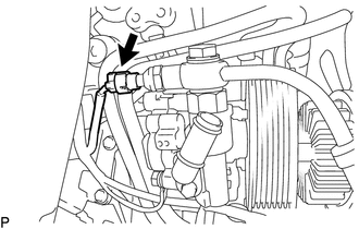
7. DISCONNECT PRESSURE FEED TUBE ASSEMBLY
|
(a) Disconnect the oil pressure switch connector. |
|
|
(b) Remove the union bolt to disconnect the pressure feed tube assembly. |
|
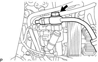
(c) Remove the gasket from the pressure feed tube assembly.
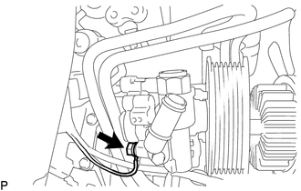
8. REMOVE VANE PUMP ASSEMBLY
|
(a) Remove the bolt to disconnect the ground wire. |
|
|
(b) Remove the 2 bolts and vane pump assembly. |
|
.png)
 Disassembly
DISASSEMBLY
PROCEDURE
1. FIX VANE PUMP ASSEMBLY
(a) Using SST, fix the vane pump assembly in a vise.
SST: 09630-00014
09631-00132
NOTICE:
When using a vise, do not overtighte ...
 Inspection
INSPECTION
PROCEDURE
1. INSPECT OIL CLEARANCE
(a) Using a micrometer and caliper gauge, measure the oil seal clearance.
Text in Illustration
*1
Pu ...
Other materials:
System Diagram
SYSTEM DIAGRAM
Communication Table
Sender
Receiver
Signal
Line
ECM
Millimeter Wave Radar Sensor Assembly
Cruise control operation signal
Accelerator pedal idle position signal
Accel overr ...
IG2 Signal Malfunction (B2788)
DESCRIPTION
This DTC is stored when the steering lock ECU (steering lock actuator or UPR
bracket assembly) detects an IG2 power supply malfunction.
HINT:
The steering lock ECU (steering lock actuator or UPR bracket assembly) is not
connected to the CAN communication system. However, the steer ...
Removal
REMOVAL
CAUTION / NOTICE / HINT
HINT:
If the bumper is damaged, there is a possibility that the installation area of
the blind spot monitor sensor may be deformed and the blind spot monitor system
may not operate correctly, so visually inspect the blind spot monitor sensor installation
area ...
