Toyota Tacoma (2015-2018) Service Manual: Data Signal Circuit between Radio Receiver and Extension Module
DESCRIPTION
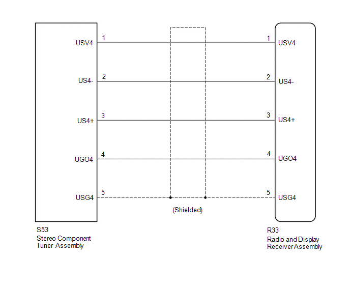
The stereo component tuner assembly sends the image data signal to the radio and display receiver assembly via this circuit.
WIRING DIAGRAM
PROCEDURE
|
1. |
CHECK NO. 1 NAVIGATION WIRE |
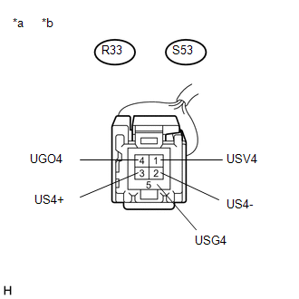
(a) Disconnect the R33 radio and display receiver assembly connector.
(b) Disconnect the S53 stereo component tuner assembly connector.
|
(c) Measure the resistance according to the value(s) in the table below. Standard Resistance:
|
|
| OK | .gif) |
PROCEED TO NEXT SUSPECTED AREA SHOWN IN PROBLEM SYMPTOMS TABLE |
| NG | |
REPLACE NO. 1 NAVIGATION WIRE |
 Data Signal Circuit between Radio Receiver and Stereo Jack Adapter
DESCRIPTION
The No. 1 stereo jack adapter assembly sends the sound data signal or image data
signal from a USB device to the radio and display receiver assembly via this circuit.
WIRING DIAGRAM
...
 Microphone Circuit between Microphone and Radio Receiver
DESCRIPTION
The radio and display receiver assembly and telephone microphone assembly are
connected to each other using the microphone connection detection signal lines.
Using this circuit, the ra ...
Other materials:
Operation Check
OPERATION CHECK
1. CHECK WINDOW LOCK SWITCH
HINT:
Before performing the window lock switch operation check, make sure that the
window lock switch is off (the switch is not pushed in).
(a) Check that the front passenger and rear windows cannot be operated from each
power window regulator swit ...
Lost Communication with ECM/PCM "A" Missing Message (U010087)
DESCRIPTION
The engine control unit and the transmission control unit are located inside
the ECM. The engine control unit intercommunicates with the transmission control
unit with the Controller Area Network (CAN).
If there is a problem in this intercommunication, the ECM stores a DTC.
...
Precaution
PRECAUTION
1. PRECAUTION
NOTICE:
When disconnecting the cable from the negative (-) battery terminal,
initialize the following systems after the cable is reconnected (See page
).
Perform the Reset Memory procedures (A/T initialization) after replacing
the automatic transmi ...
