Toyota Tacoma (2015-2018) Service Manual: Cruise Control Switch Circuit
DESCRIPTION
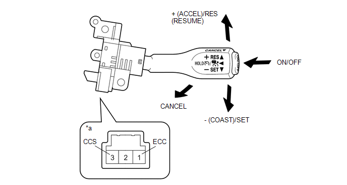
The cruise control main switch is used to turn the dynamic radar cruise control system on and off, as well as operate 7 functions: SET, - (COAST), TAP-DOWN, RES (RESUME), + (ACCEL), TAP-UP and CANCEL.
The SET, TAP-DOWN and - (COAST) functions, and the RES (RESUME), TAP-UP and + (ACCEL) functions are operated with the same switch. The cruise control main switch contains momentary type contacts for each function. The contacts close only while the cruise control main switch is being operated in the direction of the relative function arrow, and open when the cruise control main switch is released. The voltage at the terminal of the hybrid vehicle control ECU assembly changes as each of the different contacts open or close. The hybrid vehicle control ECU assembly reads this voltage and controls the SET, - (COAST), RES (RESUME), + (ACCEL), and CANCEL functions accordingly.
- Vehicle-to-vehicle distance control mode is selected by default when the dynamic radar cruise control system is turned on using the cruise control main switch (ON-OFF button).
- The operation of constant speed control mode is the same as that for a conventional cruise control system.
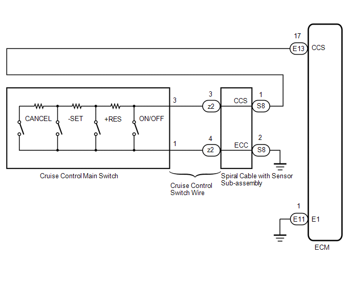
WIRING DIAGRAM
CAUTION / NOTICE / HINT
NOTICE:
- Before replacing the ECM, refer to Registration.
w/o Smart Key System: Click here
.gif)
w/ Smart Key System: Click here
- The vehicle is equipped with a Supplemental Restraint System (SRS) which
includes components such as airbags. Before servicing (including removal
or installation of parts), be sure to read the precaution for Supplemental
Restraint System.
Click here
PROCEDURE
|
1. |
READ VALUE ON TECHSTREAM |
(a) Connect the Techstream to the DLC3.
(b) Turn the ignition switch to ON.
(c) Turn the Techstream on.
(d) Enter the following menus: Powertrain / Radar Cruise1 / Data List.
(e) Read the Data List according to the display on the Techstream.
Powertrain > Radar Cruise1 > Data List
|
Tester Display |
Measurement Item |
Range |
Normal Condition |
Diagnostic Note |
|---|---|---|---|---|
|
Cancel Switch |
CANCEL switch status |
ON or OFF |
ON: CANCEL switch on OFF: CANCEL switch off |
- |
|
-SET Switch |
-SET switch status |
ON or OFF |
ON: -SET switch on OFF: -SET switch off |
- |
|
+RES Switch |
+RES switch status |
ON or OFF |
ON: +RES switch on OFF: +RES switch off |
- |
|
Cruise Main Switch Operation Condition |
Cruise control main switch (ON-OFF button) status |
ON or OFF |
ON: Cruise control main switch (ON-OFF button) pushed OFF: Cruise control main switch (ON-OFF button) not pushed |
- |
OK:
The Data List items shown in the table change according to the operation of the cruise control main switch.
| OK | .gif) |
PROCEED TO NEXT SUSPECTED AREA SHOWN IN PROBLEM SYMPTOMS TABLE |
|
.gif)
|
2. |
INSPECT CRUISE CONTROL MAIN SWITCH |
(a) Remove the cruise control main switch.
Click here
|
*a |
Component without harness connected (Cruise Control Main Switch) |
- |
- |
(b) Measure the resistance according to the value(s) in the table below.
Standard Resistance:
|
Tester Connection |
Switch Condition |
Specified Condition |
|---|---|---|
|
1 - 3 |
+ (ACCEL)/RES (RESUME) |
235 to 245 Ω |
|
1 - 3 |
- (COAST)/SET |
617 to 643 Ω |
|
1 - 3 |
CANCEL |
1,509 to 1,571 Ω |
|
1 - 3 |
Main Switch OFF |
10 kΩ or higher |
|
1 - 3 |
Main Switch ON |
Below 1 Ω |
(c) Reinstall the cruise control main switch.
| NG | |
REPLACE CRUISE CONTROL MAIN SWITCH |
|
|
3. |
CHECK CRUISE CONTROL SWITCH WIRE |
|
(a) Remove the cruise control switch wire. Click here |
|
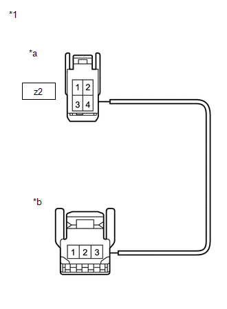
(b) Measure the resistance according to the value(s) in the table below.
Standard Resistance (Check for Open):
|
Tester Connection |
Specified Condition |
|---|---|
|
Cruise control main switch side connector terminal 3 - z2-3 |
Below 1 Ω |
|
Cruise control main switch side connector terminal 1 - z2-4 |
Below 1 Ω |
| NG | |
REPLACE CRUISE CONTROL SWITCH WIRE |
|
|
4. |
INSPECT SPIRAL CABLE WITH SENSOR SUB-ASSEMBLY |
(a) Remove the spiral cable with sensor sub-assembly.
Click here
(b) Inspect the spiral cable with sensor sub-assembly.
Click here
| NG | |
REPLACE SPIRAL CABLE WITH SENSOR SUB-ASSEMBLY |
|
|
5. |
CHECK HARNESS AND CONNECTOR (SPIRAL CABLE WITH SENSOR SUB-ASSEMBLY - ECM AND BODY GROUND) |
(a) Disconnect the S8 spiral cable with sensor sub-assembly connector.
(b) Disconnect the E13 ECM connector.
(c) Measure the resistance according to the value(s) in the table below.
Standard Resistance:
|
Tester Connection |
Condition |
Specified Condition |
|---|---|---|
|
S8-1 (CCS) - E13-17 (CCS) |
Always |
Below 1 Ω |
|
S8-2 (ECC) - Body ground |
Always |
Below 1 Ω |
|
S8-1 (CCS) or E13-17 (CCS) - Body ground |
Always |
10 kΩ or higher |
| OK | |
REPLACE ECM |
| NG | |
REPAIR OR REPLACE HARNESS OR CONNECTOR |
 Clutch Switch Circuit
DESCRIPTION
Clutch switch circuit inspection is necessary for manual transmission vehicles.
When the clutch pedal is released, the ECM receives the positive (+) battery
voltage through the ECU-IG ...
 Cruise Main Indicator Light Circuit
DESCRIPTION
When the dynamic radar cruise control system is turned on using the cruise control
main switch (ON-OFF button), the cruise control indicator (vehicle-to-vehicle distance
control mode) ...
Other materials:
GPS Mark is not Displayed
PROCEDURE
1.
CHECK CABIN
(a) Check the cabin for any object that might interrupt radio reception or additional
devices which use radio waves on the instrument panel. If such an object exists,
remove it and check if the GPS mark reappears.
HINT:
The GPS uses ex ...
Diagnostic Trouble Code Chart
DIAGNOSTIC TROUBLE CODE CHART
Air Conditioning System
DTC Code
Detection Item
Memory
See page
B1412
Ambient Temperature Sensor Circuit
Memorized
(4 seconds or more)
B1413
...
Steering Angle Sensor Unusual Bank Angle Detected (C1440)
DESCRIPTION
If the skid control ECU (master cylinder solenoid) determines that the vehicle
is being driven at a steep bank angle, the skid control ECU (master cylinder solenoid)
stores DTC C1440 while VSC operation is temporarily disabled. It is not a malfunction
if the system and sensor circ ...
