Toyota Tacoma (2015-2018) Service Manual: Components
COMPONENTS
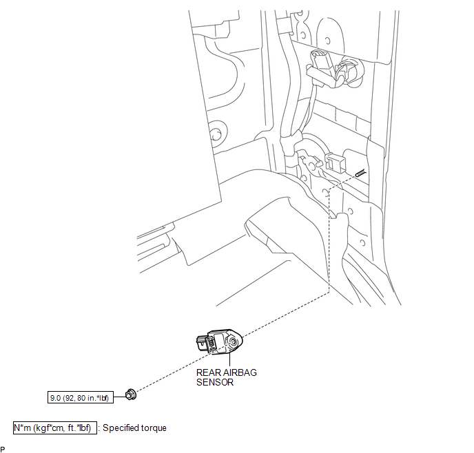
ILLUSTRATION

 Installation
INSTALLATION
CAUTION / NOTICE / HINT
HINT:
Use the same procedure for both the RH and LH sides.
The procedure described below is for the LH side.
PROCEDURE
1. INSTALL REAR AIRBA ...
Other materials:
Air Inlet Control Servo Motor
Inspection
INSPECTION
PROCEDURE
1. INSPECT AIR INLET CONTROL SERVO MOTOR
(a) Inspect the servo motor operation.
(1) Connect the positive (+) lead from the battery to terminal 1 (FRS)
and negative (-) lead to terminals 2 (REC), then check that the shaft rotates
clockwise s ...
Removal
REMOVAL
PROCEDURE
1. REMOVE REAR SEAT ASSEMBLY LH (for Double Cab)
Click here
2. REMOVE REAR SEAT ASSEMBLY RH (for Double Cab)
Click here
3. REMOVE REAR DOOR SCUFF PLATE LH (for Double Cab)
Click here
4. REMOVE REAR DOOR SCUFF PLATE RH (for Double Cab)
HINT:
Use the same procedure ...
Master Cylinder Pressure Sensor Output Malfunction (Test Mode DTC) (C1281,...,C1458)
DESCRIPTION
DTC Code
DTC Detection Condition
Trouble Area
C1281
Stored only during test mode.
Master cylinder pressure sensor circuit
Skid control ECU, master cylinder pressure sensor (master cylinder
s ...
