Toyota Tacoma (2015-2018) Service Manual: Disposal
DISPOSAL
PROCEDURE
1. DISPOSE OF BRAKE BOOSTER ACCUMULATOR ASSEMBLY
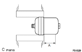
(a) Place the brake booster accumulator in a vise and cover it with a cloth.
(b) Slowly cut a hole on the brake booster accumulator side in the A portion shown in the illustration on the left. And discharge the gas and liquid inside.
NOTICE:
- As gas may spray out, cover the brake booster accumulator with a cloth when performing the operation.
- Work slowly and do not cut the hole too quickly or suddenly.
- Wear protective glasses during the operation.
(c) When the outer body of the brake booster accumulator is cut, gas and liquid discharge.
HINT:
- The gas is colorless, odorless and nonpoisonous nitrogen gas.
- The liquid is brake fluid.
 Reassembly
REASSEMBLY
PROCEDURE
1. INSTALL BRAKE BOOSTER ACCUMULATOR ASSEMBLY
(a) Place the brake booster pump in a vise with a cloth.
(b) Install the brake booster accumulator pipe, compression spring and ...
 Installation
INSTALLATION
PROCEDURE
1. INSTALL HYDRAULIC BRAKE BOOSTER
(a) Install a new brake booster gasket onto the hydraulic brake booster.
(b) Install the hydraulic brake booster with the 4 nuts.
Torque: ...
Other materials:
System Description
SYSTEM DESCRIPTION
1. UNLOCK OPERATION CONDITIONS FOR STEERING LOCK
(a) When the following condition is met, the unlock operation is performed.
The engine switch is on (ACC) or on (IG).
HINT:
When the engine switch is turned on (ACC) or on (IG) and the key and
certification ECU ( ...
Status Signal Circuit
DESCRIPTION
This circuit sends a smart key system status signal from the certification ECU
(smart key ECU assembly) to the mobile wireless charger cradle assembly. Based on
this signal, the mobile wireless charger cradle assembly suspends or resumes wireless
charging.
WIRING DIAGRAM
CAUTI ...
Differential System(w/o Differential Lock)
Precaution
PRECAUTION
1. Before disassembly, clean the outside of the front and rear differential assembly
and remove any sand and mud to prevent it from entering the assembly during disassembly
and installation.
2. When removing connected parts made of a light alloy, such as front and rear ...
