Toyota Tacoma (2015-2018) Service Manual: Installation
INSTALLATION
CAUTION / NOTICE / HINT
HINT:
- Use the same procedure for both the RH and LH sides.
- The procedure described below is for the LH side.
PROCEDURE
1. INSTALL REAR AIRBAG SENSOR
(a) Check that the ignition switch is off.
(b) Check that the battery negative (-) terminal is disconnected.
CAUTION:
Wait at least 90 seconds after disconnecting the cable from the negative (-) battery terminal to disable the SRS system.
(c) Install the rear airbag sensor with the nut.
Torque:
9.0 N·m {92 kgf·cm, 80 in·lbf}
CAUTION:
- If the rear airbag sensor has been dropped, or there are any cracks, dents or other defects in the case, bracket or connector, replace it with a new one.
- When installing the rear airbag sensor, be careful that the SRS wiring does not interfere with other parts and that it is not pinched between other parts.
(d) Check that there is no looseness in the installation parts of the rear airbag sensor.
(e) Connect the connector to the rear airbag sensor.
NOTICE:
When connecting any airbag connector, take care not to damage the airbag wire harness.
(1) Connect the connector as shown in the illustration (when locking, make sure that the outer connector locking sleeve returns to its original position and a click sound can be heard).
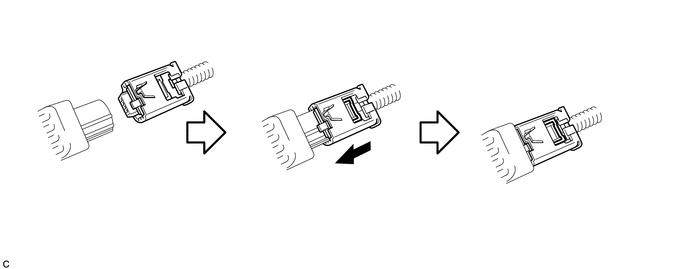
HINT:
When connected, the outer connector locking sleeve will slide. Be sure not to hold the outer connector locking sleeve while connecting, as it may result in an insecure fit.
2. INSTALL REAR SEAT 3 POINT TYPE OUTER BELT ASSEMBLY
Click here .gif)
3. CONNECT CABLE TO NEGATIVE BATTERY TERMINAL
Torque:
5.4 N·m {55 kgf·cm, 48 in·lbf}
NOTICE:
When disconnecting the cable, some systems need to be initialized after the cable is reconnected.
Click here
4. INSPECT SRS WARNING LIGHT
Click here
 Components
COMPONENTS
ILLUSTRATION
...
 On-vehicle Inspection
ON-VEHICLE INSPECTION
PROCEDURE
1. INSPECT REAR AIRBAG SENSOR (for Vehicle not Involved in Collision)
(a) Perform a diagnostic system check (See page
).
2. INSPECT REAR AIRBAG SENSOR (for Vehicl ...
Other materials:
Electrical Key Oscillator(for Front Floor)
Components
COMPONENTS
ILLUSTRATION
Installation
INSTALLATION
PROCEDURE
1. INSTALL NO. 1 INDOOR ELECTRICAL KEY ANTENNA ASSEMBLY
(a) Engage the clamp to install the No. 1 indoor electrical key antenna assembly.
(b) Connect the connector.
2. INSTALL FRONT CONSOLE BOX
(See page )
Remov ...
On-vehicle Inspection
ON-VEHICLE INSPECTION
PROCEDURE
1. INSPECT REFRIGERANT PRESSURE WITH MANIFOLD GAUGE SET
(a) This is a method to specify trouble areas by using a manifold gauge set.
Read the manifold gauge pressure when the following conditions are established.
Test conditions:
Engine has been warmed u ...
PTC Heater Circuit
DESCRIPTION
PTC HTR heater relays are closed in accordance with signals from the air conditioning
amplifier assembly and power is supplied to the quick heater assembly installed
on the radiator heater unit.
WIRING DIAGRAM
CAUTION / NOTICE / HINT
NOTICE:
Inspect the fuses for circuits rela ...
