Toyota Tacoma (2015-2018) Service Manual: Components
COMPONENTS
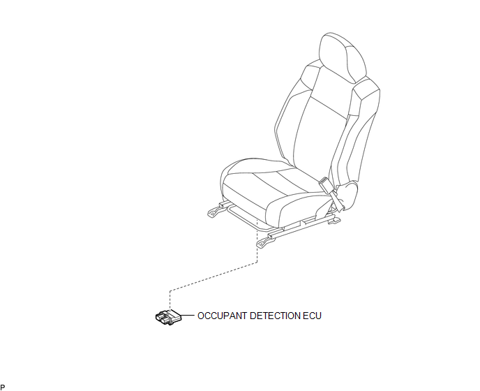
ILLUSTRATION

 On-vehicle Inspection
ON-VEHICLE INSPECTION
PROCEDURE
1. INSPECT OCCUPANT DETECTION ECU (for Vehicle not Involved in Collision)
(a) Perform a diagnostic system check (See page
).
2. INSPECT OCCUPANT DETECTION ECU (fo ...
Other materials:
Door Courtesy Switch Circuit
DESCRIPTION
The main body ECU (multiplex network Body ECU) receives a door open or closed
signal from each door courtesy light switch.
WIRING DIAGRAM
CAUTION / NOTICE / HINT
NOTICE:
Recognition code registration is necessary when replacing the main body
ECU (multiplex network bo ...
Tachometer Malfunction
DESCRIPTION
In this circuit, the meter CPU receives engine speed signals from the ECM using
the CAN communication system (CAN V1 Bus). The meter CPU displays the engine speed
calculated based on the data received from the ECM.
WIRING DIAGRAM
PROCEDURE
1.
CHECK CAN CO ...
Front Passenger Side Seat Heater does not Operate
DESCRIPTION
When the seat heater switch on the air conditioning control assembly is operated,
the air conditioning amplifier assembly receives the signal. The air conditioning
amplifier assembly receives the signal and operates the front seat heater.
WIRING DIAGRAM
CAUTION / NOTICE / HINT
...
