Toyota Tacoma (2015-2018) Service Manual: Certification Ecu
Components
COMPONENTS
ILLUSTRATION
Installation
INSTALLATION
PROCEDURE
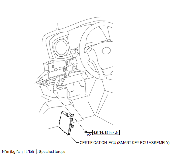
1. INSTALL CERTIFICATION ECU (SMART KEY ECU ASSEMBLY)
(a) Install the certification ECU (smart key ECU assembly) with the 2 nuts.
Torque:
6.5 N·m {66 kgf·cm, 58 in·lbf}
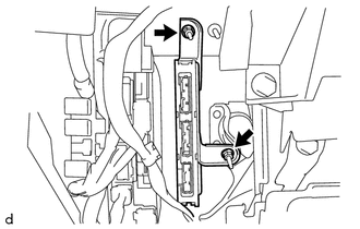
(b) Engage the clamp to install the wire harness.
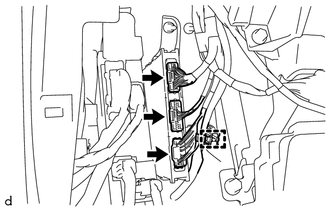
(c) Connect the 3 connectors.
2. INSTALL INSTRUMENT PANEL LOWER FINISH PANEL SUB-ASSEMBLY
(See page .gif) )
)
Removal
REMOVAL
PROCEDURE
1. REMOVE INSTRUMENT PANEL LOWER FINISH PANEL SUB-ASSEMBLY
(See page .gif) )
)
2. REMOVE CERTIFICATION ECU (SMART KEY ECU ASSEMBLY)
|
(a) Disconnect the 3 connectors. |
|
(b) Disengage the clamp to separate the wire harness.
|
(c) Remove the 2 nuts and certification ECU (smart key ECU assembly). |
|


Other materials:
Rear Center Seat Outer Belt Assembly(for Double Cab)
Components
COMPONENTS
ILLUSTRATION
Removal
REMOVAL
PROCEDURE
1. REMOVE REAR SEATBACK HINGE COVER
2. REMOVE REAR SEATBACK BOARD SUB-ASSEMBLY
3. REMOVE SEAT BELT ANCHOR COVER CAP
4. REMOVE REAR SEAT SHOULDER BELT COVER
5. REMOVE CENTER SEATBACK PAD
(a) Remove th ...
On-vehicle Inspection
ON-VEHICLE INSPECTION
CAUTION / NOTICE / HINT
HINT:
Perform "Inspection After Repair" after replacing an ignition coil assembly or
spark plug (See page ).
PROCEDURE
1. PERFORM SPARK TEST
(a) Check for DTCs (See page ).
NOTICE:
If any DTC is output, perform the troubleshooting p ...
Removal
REMOVAL
PROCEDURE
1. REMOVE MANUAL TRANSMISSION ASSEMBLY
(See page )
2. REMOVE CLUTCH RELEASE FORK SUB-ASSEMBLY
(a) Remove the clutch release fork sub-assembly with the clutch release
bearing assembly from the manual transmission assembly.
...
