Toyota Tacoma (2015-2018) Service Manual: Components
COMPONENTS
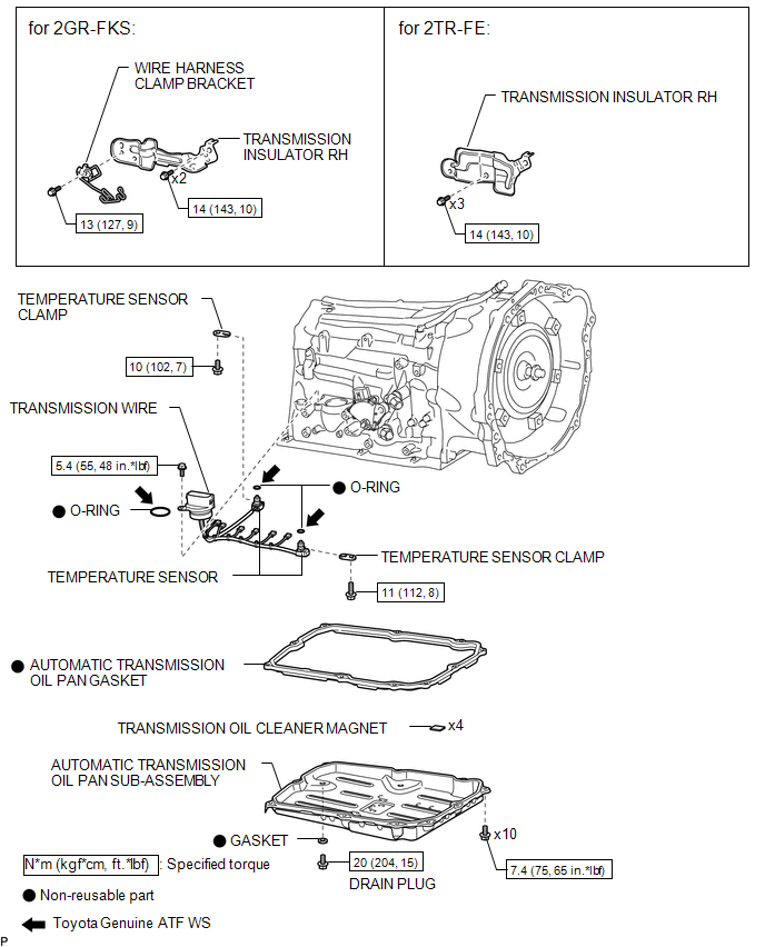
ILLUSTRATION

 Inspection
INSPECTION
PROCEDURE
1. INSPECT TRANSMISSION WIRE
(a) Measure the resistance according to the value(s) in the table below.
Text in Illustration
*a
...
Other materials:
Precaution
PRECAUTION
IGNITION SWITCH EXPRESSIONS
(a) The type of ignition switch used on this model differs according to the specifications
of the vehicle. The expressions listed in the table below are used in this section.
Expression
Ignition Switch (Position)
Engine Swi ...
Installation
INSTALLATION
PROCEDURE
1. INSTALL FRONT DIFFERENTIAL CARRIER ASSEMBLY
(a) Connect the actuator hose and connector.
(b) Install the No. 1 mounting support with the 3 bolts.
Torque:
186 N·m {1899 kgf·cm, 138 ft·lbf}
(c) Install the No. 2 mounting support with the 2 bolts.
Torque:
160 N ...
Installation
INSTALLATION
PROCEDURE
1. INSTALL FORWARD RECOGNITION CAMERA
NOTICE:
When replacing the forward recognition camera, replace it with a new
one.
Do not touch the camera lens. If the camera lens has been touched, do
not use the forward recognition camera.
If the forward reco ...
