Toyota Tacoma (2015-2018) Service Manual: Acceleration Sensor Stuck Malfunction (C1232,C1243,C1245,C1279)
DESCRIPTION
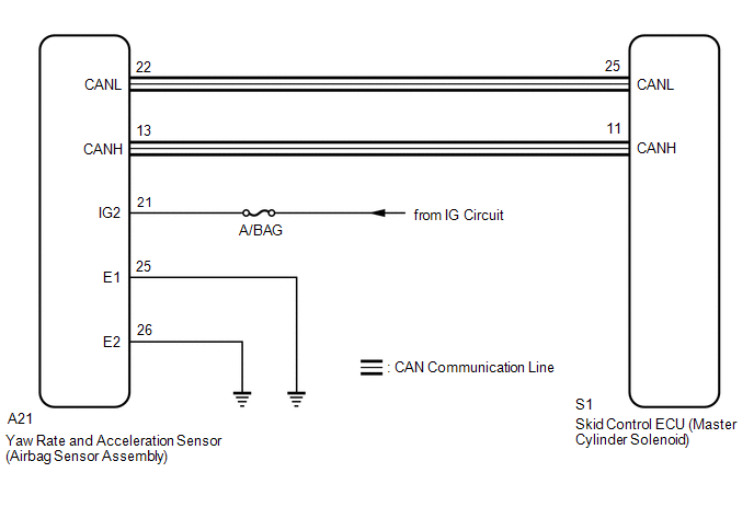
The skid control ECU (master cylinder solenoid) receives signals from the yaw rate and acceleration (airbag sensor assembly) via the CAN communication system.
The airbag sensor assembly has a built-in yaw rate and acceleration sensor and detects the vehicle's condition using 2 circuits (GL1, GL2).
If there is trouble in the bus lines between the yaw rate and acceleration sensor (airbag sensor assembly) and the CAN communication system, DTCs U0123 (yaw rate sensor communication trouble) and U0124 (acceleration sensor communication trouble) are stored.
These DTCs are also output when calibration has not been completed.
|
DTC Code |
DTC Detection Condition |
Trouble Area |
|---|---|---|
|
C1232 |
At vehicle speed of 10 km/h (6 mph) or more, signal from either GL1 or GL2 does not change for 30 seconds or more. |
|
|
C1243 |
Following condition repeats 16 times.
|
|
|
C1245 |
Following condition continues for at least 60 seconds.
|
|
|
C1279 |
Detected only during test mode |
|
WIRING DIAGRAM
CAUTION / NOTICE / HINT
NOTICE:
- When replacing the yaw rate and acceleration sensor (airbag sensor assembly),
perform zero point calibration (See page
.gif) ).
). - Inspect the fuses for circuits related to this system before performing the following inspection procedure.
HINT:
When U0073, U0100, U0123, U0124 or U0126 are output together with C1232 or C1234, inspect and repair the trouble areas indicated by U0073, U0100, U0123, U0124 or U0126 first.
PROCEDURE
|
1. |
CHECK DTC |
(a) Clear the DTCs (See page
).
(b) Turn the ignition switch off.
(c) Check if DTCs U0073, U0123, C1210 and/or C1336 are output (See page
).
|
Result |
Proceed to |
|---|---|
|
DTC U0073, U0123, C1210 and/or C1336 are not output |
A |
|
DTC U0073 and/or U0123 are output |
B |
|
DTC C1210 and/or C1336 are output |
C |
| B | .gif) |
GO TO CAN COMMUNICATION SYSTEM (HOW TO PROCEED WITH TROUBLESHOOTING) |
| C | |
REPAIR CIRCUITS INDICATED BY OUTPUT DTCS |
|
.gif)
|
2. |
CHECK AIRBAG SENSOR ASSEMBLY INSTALLATION |
(a) Check that the yaw rate and acceleration sensor (airbag sensor assembly)
is installed properly (See page
).
OK:
The sensor is tightened to the specified torque.
The sensor is not tilted.
| NG | |
INSTALL AIRBAG SENSOR ASSEMBLY CORRECTLY |
|
|
3. |
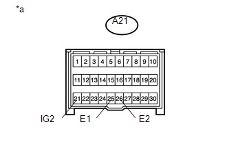
CHECK HARNESS AND CONNECTOR (IG2, E1, E2 TERMINAL) |
|
(a) Disconnect the yaw rate and acceleration sensor (airbag sensor assembly) connector. |
|
(b) Measure the voltage according to the value(s) in the table below.
Standard Voltage:
|
Tester Connection |
Switch Condition |
Specified Condition |
|---|---|---|
|
A21-21 (IG2) - Body ground |
Ignition switch ON |
11 to 14 V |
(c) Measure the resistance according to the value(s) in the table below.
Standard Resistance:
|
Tester Connection |
Condition |
Specified Condition |
|---|---|---|
|
A21-25 (E1) - Body ground |
Always |
Below 1 Ω |
|
A21-26 (E2) - Body ground |
Always |
Below 1 Ω |
|
*a |
Front view of wire harness connector (to Yaw Rate and Acceleration Sensor (Airbag Sensor Assembly)) |
|
Result |
Proceed to |
|---|---|
|
OK (When troubleshooting in accordance with Diagnostic Trouble Code Chart) |
A |
|
OK (When troubleshooting in accordance with Problem Symptoms Table) |
B |
|
NG |
C |
| A | |
REPLACE AIRBAG SENSOR ASSEMBLY |
| B | |
PROCEED TO NEXT SUSPECTED AREA SHOWN IN PROBLEM SYMPTOMS TABLE |
| C | |
REPAIR OR REPLACE HARNESS OR CONNECTOR |
 SM Solenoid Circuit (C1225-C1228,C1468,C1469,C146A,C146B)
DESCRIPTION
The solenoid goes on when signals are received from the skid control ECU (master
cylinder solenoid) and controls the pressure action on the wheel cylinders thus
controlling the brakin ...
 Low Power Supply Voltage Malfunction (C1241)
DESCRIPTION
If there is a problem with the skid control ECU (master cylinder solenoid) power
supply circuit, the skid control ECU outputs the DTC and prohibits operation under
the fail-safe funct ...
Other materials:
Manual transmission
■ Shifting the shift lever
6-speed models
Fully depress the clutch pedal before operating the shift lever, and then release
it slowly.
5-speed models
Fully depress the clutch pedal before operating the shift lever, and then release
it slowly.
■Maximum allowable speed
Obse ...
Registration
REGISTRATION
CAUTION / NOTICE / HINT
HINT:
Register a new recognition code when replacing the door control transmitter
module set sub-assembly or the door control receiver.
Add mode is used to retain the already registered codes while registering
a new recognition code. This m ...
Before Starting Adjustment
BEFORE STARTING ADJUSTMENT
CAUTION / NOTICE / HINT
NOTICE:
When replacing the windshield glass of a vehicle equipped with a forward recognition
camera, make sure to use a Toyota genuine part. If a non-Toyota genuine part is
used, the forward recognition camera may not be able to be installed ...
