Toyota Tacoma (2015-2018) Service Manual: Air Outlet Damper Control Servo Motor Circuit (B1443/43)
DESCRIPTION
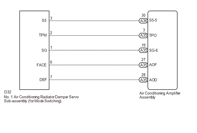
This No. 1 air conditioning radiator damper servo sub-assembly (for mode switching) is controlled by the air conditioning amplifier assembly and moves the mode damper to the desired position.
|
DTC No. |
DTC Detection Condition |
Trouble Area |
|---|---|---|
|
B1443/43 |
Mode damper position sensor value does not change even if air conditioning amplifier assembly operates mode damper servo motor. |
|
WIRING DIAGRAM
PROCEDURE
|
1. |
READ VALUE USING TECHSTREAM |
(a) Connect the Techstream to the DLC3.
(b) Turn the ignition switch to ON.
(c) Turn the Techstream on.
(d) Operate the mode switch.
(e) Enter the following menus: Body Electrical / Air Conditioner / Data List.
(f) Check the value(s) by referring to the table below.
Air Conditioner|
Tester Display |
Measurement Item/Range |
Normal Condition |
Diagnostic Note |
|---|---|---|---|
|
Air Outlet Damper Position |
Mode damper servo motor actual position / Min.: -14.0% Max.: 113.5% |
FACE: 0.0% DEF: 100.0% |
- |
|
Air Outlet Damper Target |
Mode damper servo motor target position / Min.: -14.0% Max.: 113.5% |
FACE: 0.0% DEF: 100.0% |
- |
OK:
The display is as specified in the Normal Condition column.
|
Result |
Proceed to |
|---|---|
|
NG |
A |
|
OK (When troubleshooting according to Problem Symptoms Table) |
B |
|
OK (When troubleshooting according to the DTC) |
C |
| B | .gif) |
PROCEED TO NEXT SUSPECTED AREA SHOWN IN PROBLEM SYMPTOMS TABLE |
| C | |
REPLACE AIR CONDITIONING AMPLIFIER ASSEMBLY |
|
.gif)
|
2. |
INSPECT NO. 1 AIR CONDITIONING RADIATOR DAMPER SERVO SUB-ASSEMBLY (FOR MODE SWITCHING) |
(a) Remove the No. 1 air conditioning radiator damper servo sub-assembly (for
mode switching) (See page .gif) ).
).
(b) Inspect the No. 1 air conditioning radiator damper servo sub-assembly (for
mode switching) (See page ).
| NG | |
REPLACE NO. 1 AIR CONDITIONING RADIATOR DAMPER SERVO SUB-ASSEMBLY (FOR MODE SWITCHING) |
|
|
3. |
CHECK HARNESS AND CONNECTOR (NO. 1 AIR CONDITIONING RADIATOR DAMPER SERVO SUB-ASSEMBLY - AIR CONDITIONING AMPLIFIER ASSEMBLY) |
(a) Disconnect the D32 No. 1 air conditioning radiator damper servo sub-assembly (for mode switching) connector.
(b) Disconnect the A35 air conditioning amplifier assembly connector.
(c) Measure the resistance according to the value(s) in the table below.
Standard Resistance:
|
Tester Connection |
Condition |
Specified Condition |
|---|---|---|
|
D32-6 (FACE) - A35-27 (AOF) |
Always |
Below 1 Ω |
|
D32-7 (DEF) - A35-28 (AOD) |
Always |
Below 1 Ω |
|
D32-6 (FACE) or A35-27 (AOF) |
Always |
10 kΩ or higher |
|
D32-7 (DEF) or A35-28 (AOD) |
Always |
10 kΩ or higher |
| OK | |
REPLACE AIR CONDITIONING AMPLIFIER ASSEMBLY |
| NG | |
REPAIR OR REPLACE HARNESS OR CONNECTOR |
 Lost Communication with ECM (U0100,U0142,U0155)
DESCRIPTION
DTC No.
DTC Detecting Condition
Trouble Area
U0100
No communication with ECM
CAN communication system
...
 Air Outlet Damper Position Sensor Circuit (B1433/33)
DESCRIPTION
This sensor detects the position of the mode damper and sends the appropriate
signals to the air conditioning amplifier assembly. The position sensor is built
into the No. 1 air condi ...
Other materials:
Certification ECU Vehicle Information Reading/Writing Process Malfunction (B15F7)
DESCRIPTION
This DTC is stored when items controlled by the certification ECU (smart key
ECU assembly) cannot be customized via the navigation system vehicle customization
screen.
HINT:
The certification ECU (smart key ECU assembly) controls the smart key system
related items that are custo ...
Customize Parameters
CUSTOMIZE PARAMETERS
PROCEDURE
1. CUSTOMIZE WIRELESS DOOR LOCK CONTROL SYSTEM (w/ Smart Key System)
HINT:
The following items can be customized.
NOTICE:
When the customer requests a change in a function, first make sure that
the function can be customized.
Be sure to make a not ...
Data List / Active Test
DATA LIST / ACTIVE TEST
1. DATA LIST
HINT:
Using the Techstream to read the Data List allows the values or states of switches,
sensors, actuators and other items to be read without removing any parts. This non-intrusive
inspection can be very useful because intermittent conditions or signals ...
