Toyota Tacoma (2015-2018) Service Manual: Air Outlet Damper Position Sensor Circuit (B1433/33)
DESCRIPTION
This sensor detects the position of the mode damper and sends the appropriate signals to the air conditioning amplifier assembly. The position sensor is built into the No. 1 air conditioning radiator damper servo sub-assembly (for mode switching).
|
DTC No. |
DTC Detection Condition |
Trouble Area |
|---|---|---|
|
B1433/33 |
Short to ground or power source circuit mode damper position sensor circuit. |
|
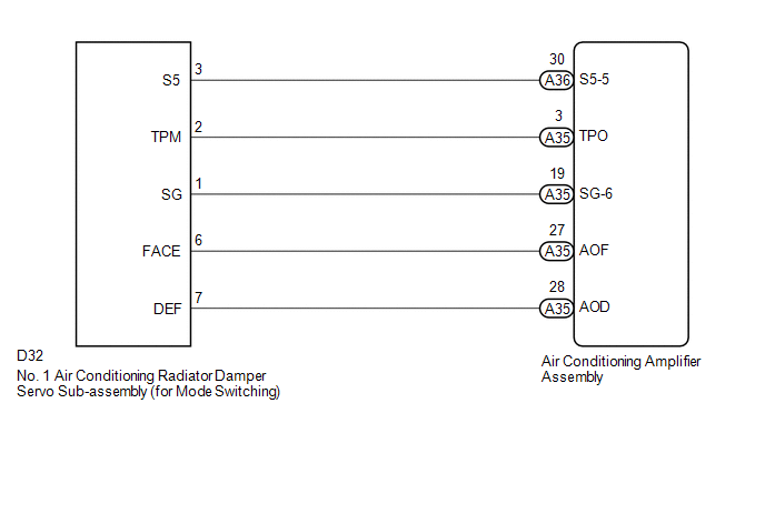
WIRING DIAGRAM
PROCEDURE
|
1. |
READ VALUE USING TECHSTREAM |
(a) Connect the Techstream to the DLC3.
(b) Turn the ignition switch to ON.
(c) Turn the Techstream on.
(d) Operate the mode switch.
(e) Enter the following menus: Body Electrical / Air Conditioner / Data List.
(f) Check the value(s) by referring to the table below.
Air Conditioner|
Tester Display |
Measurement Item/Range |
Normal Condition |
Diagnostic Note |
|---|---|---|---|
|
Air Outlet Damper Position |
Mode damper servo motor actual position / Min.: -14.0% Max.: 113.5% |
FACE: 0.0% DEF: 100.0% |
- |
|
Air Outlet Damper Target |
Mode damper servo motor target position / Min.: -14.0% Max.: 113.5% |
FACE: 0.0% DEF: 100.0% |
- |
OK:
The display is as specified in the Normal Condition column.
|
Result |
Proceed to |
|---|---|
|
NG |
A |
|
OK (When troubleshooting according to Problem Symptoms Table) |
B |
|
OK (When troubleshooting according to the DTC) |
C |
| B | .gif) |
PROCEED TO NEXT SUSPECTED AREA SHOWN IN PROBLEM SYMPTOMS TABLE |
| C | |
REPLACE AIR CONDITIONING AMPLIFIER ASSEMBLY |
|
.gif)
|
2. |
INSPECT NO. 1 AIR CONDITIONING RADIATOR DAMPER SERVO SUB-ASSEMBLY (FOR MODE SWITCHING) |
(a) Remove the No. 1 air conditioning radiator damper servo sub-assembly (for
mode switching) (See page .gif) ).
).
(b) Inspect the No. 1 air conditioning radiator damper servo sub-assembly (for
mode switching) (See page ).
| NG | |
REPLACE NO. 1 AIR CONDITIONING RADIATOR DAMPER SERVO SUB-ASSEMBLY (FOR MODE SWITCHING) |
|
|
3. |
CHECK HARNESS AND CONNECTOR (NO. 1 AIR CONDITIONING RADIATOR DAMPER SERVO SUB-ASSEMBLY - AIR CONDITIONING AMPLIFIER ASSEMBLY) |
(a) Disconnect the D32 No. 1 air conditioning radiator damper servo sub-assembly (for mode switching) connector.
(b) Disconnect the A35 air conditioning amplifier assembly connector.
(c) Measure the resistance according to the value(s) in the table below.
Standard Resistance:
|
Tester Connection |
Condition |
Specified Condition |
|---|---|---|
|
D32-3 (S5) - A36-30 (S5-5) |
Always |
Below 1 Ω |
|
D32-2 (TPM) - A35-3 (TPO) |
Always |
Below 1 Ω |
|
D32-1 (SG) - A35-19 (SG-6) |
Always |
Below 1 Ω |
|
D32-3 (S5) or A36-30 (S5-5) - Body ground |
Always |
10 kΩ or higher |
|
D32-2 (TPM) or A35-3 (TPO) - Body ground |
Always |
10 kΩ or higher |
|
D32-1 (SG) or A35-19 (SG-6) - Body ground |
Always |
10 kΩ or higher |
| OK | |
REPLACE AIR CONDITIONING AMPLIFIER ASSEMBLY |
| NG | |
REPAIR OR REPLACE HARNESS OR CONNECTOR |
 Air Outlet Damper Control Servo Motor Circuit (B1443/43)
DESCRIPTION
This No. 1 air conditioning radiator damper servo sub-assembly (for mode switching)
is controlled by the air conditioning amplifier assembly and moves the mode damper
to the desired p ...
 Air Mix Damper Position Sensor Circuit (Driver Side) (B1436/36)
DESCRIPTION
This sensor detects the position of the air mix damper (for driver side) and
sends the appropriate signals to the air conditioning amplifier assembly. The position
sensor is built int ...
Other materials:
IG2 Signal Malfunction (B2788)
DESCRIPTION
This DTC is stored when the steering lock ECU (steering lock actuator or UPR
bracket assembly) detects an IG2 power supply malfunction.
HINT:
The steering lock ECU (steering lock actuator or UPR bracket assembly) is not
connected to the CAN communication system. However, the steer ...
LVDS Signal Malfunction (from Extension Module) (B1532)
DESCRIPTION
The stereo component tuner assembly and the radio and display receiver assembly
are connected by an LVDS communication line.
This DTC is stored when an LVDS communication error occurs between the stereo
component tuner assembly and the radio and display receiver assembly.
...
Transmitter ID not Received in Main Mode (C2126/26)
DESCRIPTION
After all transmitter IDs are registered, DTC C2126/26 is stored in the tire
pressure warning ECU and receiver and the tire pressure warning light blinks for
1 minute and then illuminates.
When the tire pressure warning ECU and receiver successfully receives radio waves
from all ...
