Toyota Tacoma (2015-2018) Service Manual: Air Mix Damper Control Servo Motor Circuit (Passenger Side) (B1441/41)
DESCRIPTION
This No. 2 air conditioning radiator damper servo sub-assembly (for front passenger side air mix) is controlled by the air conditioning amplifier assembly and moves the air mix damper (for front passenger side) to the desired position.
|
DTC No. |
DTC Detection Condition |
Trouble Area |
|---|---|---|
|
B1441/41 |
Air mix damper position sensor (for front passenger side) value does not change even if air conditioning amplifier assembly operates air mix damper servo motor (for front passenger side). |
|
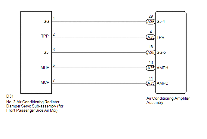
WIRING DIAGRAM
PROCEDURE
|
1. |
READ VALUE USING TECHSTREAM |
(a) Connect the Techstream to the DLC3.
(b) Turn the ignition switch to ON.
(c) Turn the Techstream on.
(d) Operate the front passenger side temperature switch.
(e) Enter the following menus: Body Electrical / Air Conditioner / Data List.
(f) Check the value(s) by referring to the table below.
Air Conditioner|
Tester Display |
Measurement Item/Range |
Normal Condition |
Diagnostic Note |
|---|---|---|---|
|
Air Mix Damper Position (Passenger Side) |
Air mix damper servo motor (for front passenger side) actual position / Min.: -14.0% Max.: 113.5% |
MAX COOL: 0.0% MAX HOT: 100.0% |
- |
|
Air Mix Damper Target (Passenger Side) |
Air mix damper servo motor (for front passenger side) target position / Min.: -14.0% Max.: 113.5% |
MAX COOL: 0.0% MAX HOT: 100.0% |
- |
OK:
The display is as specified in the Normal Condition column.
|
Result |
Proceed to |
|---|---|
|
NG |
A |
|
OK (When troubleshooting according to Problem Symptoms Table) |
B |
|
OK (When troubleshooting according to the DTC) |
C |
| B | .gif) |
PROCEED TO NEXT SUSPECTED AREA SHOWN IN PROBLEM SYMPTOMS TABLE |
| C | |
REPLACE AIR CONDITIONING AMPLIFIER ASSEMBLY |
|
.gif)
|
2. |
INSPECT NO. 2 AIR CONDITIONING RADIATOR DAMPER SERVO SUB-ASSEMBLY (FOR FRONT PASSENGER SIDE AIR MIX) |
(a) Remove the No. 2 air conditioning radiator damper servo sub-assembly (for
front passenger side air mix) (See page .gif) ).
).
(b) Inspect the No. 2 air conditioning radiator damper servo sub-assembly (for
front passenger side air mix) (See page ).
| NG | |
REPLACE NO. 2 AIR CONDITIONING RADIATOR DAMPER SERVO SUB-ASSEMBLY (FOR FRONT PASSENGER SIDE AIR MIX) |
|
|
3. |
CHECK HARNESS AND CONNECTOR (NO. 2 AIR CONDITIONING RADIATOR DAMPER SERVO SUB-ASSEMBLY - AIR CONDITIONING AMPLIFIER ASSEMBLY) |
(a) Disconnect the D31 No. 2 air conditioning radiator damper servo sub-assembly (for front passenger side air mix) connector.
(b) Disconnect the A35 air conditioning amplifier assembly connector.
(c) Measure the resistance according to the value(s) in the table below.
Standard Resistance:
|
Tester Connection |
Condition |
Specified Condition |
|---|---|---|
|
D31-6 (MHP) - A35-13 (AMPH) |
Always |
Below 1 Ω |
|
D31-7 (MCP) - A35-14 (AMPC) |
Always |
Below 1 Ω |
|
D31-6 (MHP) or A35-13 (AMPH) - Body ground |
Always |
10 kΩ or higher |
|
D31-7 (MCP) or A35-14 (AMPC) - Body ground |
Always |
10 kΩ or higher |
| OK | |
REPLACE AIR CONDITIONING AMPLIFIER ASSEMBLY |
| NG | |
REPAIR OR REPLACE HARNESS OR CONNECTOR |
 Room Temperature Sensor Circuit (B1411/11)
DESCRIPTION
The cooler thermistor (room temperature sensor) is installed in the instrument
panel to detect the cabin temperature which is used to control the air conditioning
system AUTO mode. Th ...
 Ambient Temperature Sensor Circuit (B1412/12)
DESCRIPTION
The ambient temperature sensor is installed in front of the condenser to detect
the ambient temperature which is used to control the air conditioning system AUTO
mode. This sensor is ...
Other materials:
Theft deterrent system
Engine immobilizer system
The vehicle’s keys have built-in transponder chips that prevent the engine from
starting if the key has not been previously registered in the vehicle’s on-board
computer.
Never leave the keys inside the vehicle when you leave the vehicle.
The indicator light fl ...
Steering Angle Sensor Internal Circuit (C1433)
DESCRIPTION
The skid control ECU (brake actuator assembly) outputs this DTC when it receives
an internal malfunction signal from the steering angle sensor.
DTC No.
Detection Item
DTC Detection Condition
Trouble Area
C1433
St ...
Removal
REMOVAL
PROCEDURE
1. REMOVE FUEL DELIVERY PIPE ASSEMBLY LH (FUEL PRESSURE SENSOR)
(See page )
NOTICE:
Do not remove the fuel pressure sensor from the fuel delivery pipe sub-assembly
LH.
If a fuel pressure sensor is removed, replace the fuel delivery pipe
sub-assembly LH (fu ...
