Toyota Tacoma (2015-2018) Service Manual: Room Temperature Sensor Circuit (B1411/11)
DESCRIPTION
The cooler thermistor (room temperature sensor) is installed in the instrument panel to detect the cabin temperature which is used to control the air conditioning system AUTO mode. The resistance of the cooler thermistor (room temperature sensor) changes in accordance with the cabin temperature. As the temperature decreases, the resistance increases. As the temperature increases, the resistance decreases.
The air conditioning amplifier assembly applies a voltage (5 V) to the cooler thermistor (room temperature sensor) and reads voltage changes due to changes in the resistance of the cooler thermistor (room temperature sensor).
|
DTC No. |
DTC Detection Condition |
Trouble Area |
|---|---|---|
|
B1411/11 |
Open or short in cooler thermistor (room temperature sensor) circuit |
|
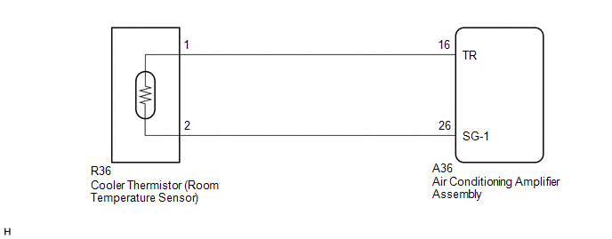
WIRING DIAGRAM
PROCEDURE
|
1. |
READ VALUE USING TECHSTREAM |
(a) Connect the Techstream to the DLC3.
(b) Turn the ignition switch to ON.
(c) Turn the Techstream on.
(d) Enter the following menus: Body Electrical / Air Conditioner / Data List.
(e) Check the value(s) by referring to the table below.
Air Conditioner|
Tester Display |
Measurement Item/Range |
Normal Condition |
Diagnostic Note |
|---|---|---|---|
|
Room Temperature Sensor |
Cooler thermistor (room temperature sensor) / min.: -6.50°C (20.30°F) max.: 57.25°C (135.05°F) |
Actual cabin temperature displayed |
- |
OK:
The display is as specified in the Normal Condition column.
|
Result |
Proceed to |
|---|---|
|
NG |
A |
|
OK (When troubleshooting according to Problem Symptoms Table) |
B |
|
OK (When troubleshooting according to the DTC) |
C |
| B | .gif) |
PROCEED TO NEXT SUSPECTED AREA SHOWN IN PROBLEM SYMPTOMS TABLE |
| C | |
REPLACE AIR CONDITIONING AMPLIFIER ASSEMBLY |
|
.gif)
|
2. |
INSPECT COOLER THERMISTOR (ROOM TEMPERATURE SENSOR) |
(a) Remove the cooler thermistor (room temperature sensor) (See page
.gif) ).
).
(b) Inspect the cooler thermistor (room temperature sensor) (See page
).
| NG | |
REPLACE COOLER THERMISTOR (ROOM TEMPERATURE SENSOR) |
|
|
3. |
CHECK HARNESS AND CONNECTOR (COOLER THERMISTOR (ROOM TEMPERATURE SENSOR) - AIR CONDITIONING AMPLIFIER ASSEMBLY) |
(a) Disconnect the R36 cooler thermistor (room temperature sensor) connector.
(b) Disconnect the A36 air conditioning amplifier assembly connector.
(c) Measure the resistance according to the value(s) in the table below.
Standard Resistance:
|
Tester Connection |
Condition |
Specified Condition |
|---|---|---|
|
R36-1 - A36-16 (TR) |
Always |
Below 1 Ω |
|
R36-2 - A36-26 (SG-1) |
Always |
Below 1 Ω |
|
R36-1 or A36-16 (TR) - Body ground |
Always |
10 kΩ or higher |
|
R36-2 or A36-26 (SG-1) - Body ground |
Always |
10 kΩ or higher |
| OK | |
REPLACE AIR CONDITIONING AMPLIFIER ASSEMBLY |
| NG | |
REPAIR OR REPLACE HARNESS OR CONNECTOR |
 Air Inlet Damper Control Servo Motor Circuit (B1442/42)
DESCRIPTION
This No. 1 air conditioning servo assembly (fresh/recirculation damper) is controlled
by the air conditioning amplifier assembly and moves the air inlet damper to the
desired position ...
 Air Mix Damper Control Servo Motor Circuit (Passenger Side) (B1441/41)
DESCRIPTION
This No. 2 air conditioning radiator damper servo sub-assembly (for front passenger
side air mix) is controlled by the air conditioning amplifier assembly and moves
the air mix damper ...
Other materials:
Disassembly
DISASSEMBLY
PROCEDURE
1. FIX VANE PUMP
(a) Using SST, fix the vane pump assembly in a vise.
SST: 09630-00014
09631-00132
NOTICE:
When using a vise, do not overtighten it.
2. REMOVE VANE PUMP OIL RESERVOIR SUB-ASSEMBLY
(a) Remove the 3 bolts and vane pump oil reservoir.
(b) Remove the O-r ...
Lubrication System
On-vehicle Inspection
ON-VEHICLE INSPECTION
PROCEDURE
1. INSPECT ENGINE OIL LEVEL
(a) Warm up the engine, and then stop the engine and wait for 5 minutes.
(b) Check that the engine oil level is between the low level and full level marks
on the dipstick.
If low, check for leakage and add en ...
Removal
REMOVAL
PROCEDURE
1. PRECAUTION
CAUTION:
Be sure to read Precaution thoroughly before servicing (See page
).
NOTICE:
After turning the ignition switch off, waiting time may be required before disconnecting
the cable from the negative (-) battery terminal. Therefore, make sure to read the
...
