Toyota Tacoma (2015-2018) Service Manual: Removal
REMOVAL
PROCEDURE
1. REMOVE FUEL DELIVERY PIPE ASSEMBLY LH (FUEL PRESSURE SENSOR)
(See page .gif) )
)
NOTICE:
- Do not remove the fuel pressure sensor from the fuel delivery pipe sub-assembly LH.
- If a fuel pressure sensor is removed, replace the fuel delivery pipe sub-assembly LH (fuel pressure sensor) with a new one.
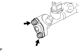
2. REMOVE FUEL PIPE PLUG SUB-ASSEMBLY
(a) Secure the fuel delivery pipe assembly LH in a vise between aluminum plates.
NOTICE:
Do not overtighten the vise.
(b) Remove the dust cap sub-assembly from the fuel pipe plug sub-assembly.
|
(c) Using a 5 mm hexagon wrench, remove the 2 bolts and fuel pipe plug sub-assembly. |
|
(d) Remove the gasket from the fuel pipe plug sub-assembly.
|
(e) Remove the O-ring, No. 3 fuel injector back-up ring, No. 2 fuel injector back-up ring and No. 1 fuel injector back-up ring from the fuel pipe plug sub-assembly. Text in Illustration
|
|
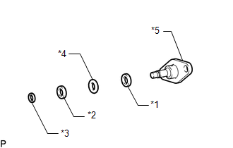
(f) Remove the fuel delivery pipe assembly LH from the vise.
 Components
COMPONENTS
ILLUSTRATION
...
 Inspection
INSPECTION
PROCEDURE
1. INSPECT FUEL DELIVERY PIPE SUB-ASSEMBLY LH (FUEL PRESSURE SENSOR)
NOTICE:
Do not remove the fuel pressure sensor from the fuel delivery pipe sub-assembly
LH.
...
Other materials:
On-vehicle Inspection
ON-VEHICLE INSPECTION
PROCEDURE
1. INSPECT CURTAIN SHIELD AIRBAG ASSEMBLY (for Vehicle not Involved in Collision)
(a) Perform a diagnostic system check (See page
).
(b) With the curtain shield airbag assembly installed on the vehicle,
perform a visual check. If there are any def ...
System Diagram
SYSTEM DIAGRAM
Transmitting ECU (Transmitter)
Receiving ECU
Signal
Communication Method
4 wheel drive control ECU
Skid control ECU (Brake actuator assembly)
Rear differential lock status signal
H ...
Power outlets (12 VDC)
Please use as a power supply for electronic goods that use less than 12 VDC/10
A (power consumption of 120 W).
When using electronic goods, make sure that the power consumption of all the
connected power outlets is less than 120 W.
■The power outlets can be used when
The engine switch ...
