Toyota Tacoma (2015-2018) Service Manual: Components
COMPONENTS
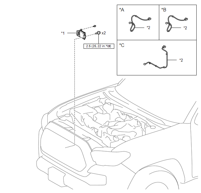
ILLUSTRATION
|
*A |
for Type A |
*B |
for Type B |
|
*C |
for Type C |
- |
- |
|
*1 |
MILLIMETER WAVE RADAR SENSOR ASSEMBLY |
*2 |
MILLIMETER WAVE RADAR WIRE |
.png) |
N*m (kgf*cm, ft.*lbf): Specified torque |
- |
- |

 Adjustment
ADJUSTMENT
CAUTION / NOTICE / HINT
CAUTION:
Radiofrequency radiation exposure information:
This equipment complies with FCC radiation exposure limits set forth
for an uncontrolled envir ...
Other materials:
Transmission Fluid Temperature Sensor "A" Circuit Short To Ground (P071011)
DESCRIPTION
The No. 1 ATF temperature sensor converts the fluid temperature into a resistance
value for use by the ECM.
The ECM applies a voltage to the temperature sensor through terminal THO1 of
the ECM.
The sensor resistance changes with the ATF temperature. As the temperature becomes
hi ...
Inspection
INSPECTION
PROCEDURE
1. INSPECT FRONT SEATBACK HEATER ASSEMBLY
(a) Check the operation of the front seatback heater assembly.
(1) Apply battery voltage and check the operation of the front seatback
heater assembly.
OK:
Connection
Conditio ...
Portable Player cannot be Connected Manually/Automatically
CAUTION / NOTICE / HINT
HINT:
Some versions of "Bluetooth" compatible audio players may not function, or the
function may be limited using the radio and display receiver assembly, even if the
portable audio player itself can play files (See page
).
PROCEDURE
1.
...
