Toyota Tacoma (2015-2018) Service Manual: Registration
REGISTRATION
PROCEDURE
1. BEFORE REGISTRATION
NOTICE:
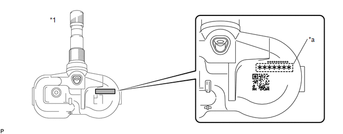
The transmitter ID is written on the tire pressure warning valve and transmitter. It is not possible to read the transmitter ID after installing the tire onto the wheel. Therefore, make a note of the transmitter ID before installing the tire.
(a) In case of tire pressure warning ECU and receiver replacement:
(1) Read the registered transmitter IDs that are stored in the old ECU using the Techstream and write them down.
(2) If reading the stored transmitter IDs is impossible due to malfunctions of components such as the tire pressure warning ECU and receiver, remove the tires from the wheels and check the IDs located on the tire pressure warning valve and transmitters.
(b) In case of tire pressure warning valve and transmitter replacement:
(1) Take a note of the 7-digit number (transmitter ID) written on the tire pressure warning valve and transmitter.
 Text in Illustration
|
*1 |
Tire Pressure Warning Valve and Transmitter |
- |
- |
|
*a |
Transmitter ID (7-digit Number) |
- |
- |
2. REGISTER TRANSMITTER ID (USING TECHSTREAM)
HINT:
- The previously registered IDs will be cleared from memory when registration is completed.
- If the ID registration step is not completed within 300 seconds, ID registration will be canceled.
(a) Set the tire pressure to the specified value (See page
.gif) ).
).
(b) Turn the ignition switch off.
(c) Connect the Techstream to the DLC3.
(d) Turn the ignition switch to ON and the Techstream on.
(e) Enter the following menus: Chassis / Tire Pressure Monitor / Utility / ID Registration.
(f) Perform the procedure displayed on the Techstream.
3. CONFIRMATION OF TRANSMITTER ID REGISTRATION
NOTICE:
- It may take a few minutes until the values are displayed. If the values
are not displayed after a few minutes, perform troubleshooting according
to the inspection procedure for DTCs C2121/21 to C2124/24 (See page
).
- If the transmitter IDs have not been registered, DTC C2171/71 is stored in the tire pressure warning ECU and receiver after 3 minutes or more.
- If normal pressure values are displayed, the transmitter IDs have been registered correctly.
- If the tire pressure values are not displayed after a few minutes, the transmitter IDs may be incorrect or the system may have a malfunction.
- After all transmitter IDs are registered, DTC C2126/26 is stored in the tire pressure warning ECU and receiver and the tire pressure warning light blinks for 1 minute and then illuminates. When the tire pressure warning ECU and receiver successfully receives signals from all the transmitters whose IDs are stored in the ECU, DTC C2126/26 is cleared and the tire pressure warning light goes off.
(a) Enter the following menus: Chassis / Tire Pressure Monitor / Data List.
Tire Pressure Monitor|
Tester Display |
Measurement Item/Range |
Normal Condition |
Diagnostic Note |
|---|---|---|---|
|
ID 1 Tire Inflation Pressure |
ID1 tire inflation pressure/ min.: Absolute pressure (abs) / 0 kPa (0 kgf/cm2, 0 psi), Relative pressure (Gauge) / 0 kPa (0 kgf/cm2, 0 psi) max.: Absolute pressure (abs) / 480 kPa (4.9 kgf/cm2, 70 psi), Relative pressure (Gauge) / 380 kPa (3.9 kgf/ cm2, 55 psi) |
Actual tire inflation pressure |
If N/A is displayed, data has not been received.*1 |
|
ID 2 Tire Inflation Pressure |
ID2 tire inflation pressure/ min.: Absolute pressure (abs) / 0 kPa (0 kgf/cm2, 0 psi), Relative pressure (Gauge) / 0 kPa (0 kgf/cm2, 0 psi) max.: Absolute pressure (abs) / 480 kPa (4.9 kgf/cm2, 70 psi), Relative pressure (Gauge) / 380 kPa (3.9 kgf/ cm2, 55 psi) |
Actual tire inflation pressure |
If N/A is displayed, data has not been received.*1 |
|
ID 3 Tire Inflation Pressure |
ID3 tire inflation pressure/ min.: Absolute pressure (abs) / 0 kPa (0 kgf/cm2, 0 psi), Relative pressure (Gauge) / 0 kPa (0 kgf/cm2, 0 psi) max.: Absolute pressure (abs) / 480 kPa (4.9 kgf/cm2, 70 psi), Relative pressure (Gauge) / 380 kPa (3.9 kgf/ cm2, 55 psi) |
Actual tire inflation pressure |
If N/A is displayed, data has not been received.*1 |
|
ID 4 Tire Inflation Pressure |
ID4 tire inflation pressure/ min.: Absolute pressure (abs) / 0 kPa (0 kgf/cm2, 0 psi), Relative pressure (Gauge) / 0 kPa (0 kgf/cm2, 0 psi) max.: Absolute pressure (abs) / 480 kPa (4.9 kgf/cm2, 70 psi), Relative pressure (Gauge) / 380 kPa (3.9 kgf/ cm2, 55 psi) |
Actual tire inflation pressure |
If N/A is displayed, data has not been received.*1 |
HINT:
*1: It may take a few minutes until the values are displayed. If the values are not displayed after a few minutes, perform troubleshooting according to the inspection procedure for DTCs C2121/21 to C2124/24.
(b) Reduce the tire inflation pressure of each tire 40 kPa (0.4 kgf/cm2, 5.8 psi) or more within 30 seconds, and check that the "ID Tire Inflation Pressure" data is updated and that the actual tire inflation pressures are displayed.
(c) After confirming that all of the tire inflation pressure values (except the compact spare tire) have been updated, adjust the tire inflation pressure to the specified value, press the tire pressure warning reset switch and perform initialization.
4. TIRE POSITION IDENTIFICATION (USING TECHSTREAM) (w/ Tire Inflation Pressure Display Function)
(a) Set the tire pressure to the specified value (See page
).
(b) Turn the ignition switch off.
(c) Connect the Techstream to the DLC3.
(d) Turn the ignition switch to ON and the Techstream on.
(e) Enter the following menus: Chassis / Tire Pressure Monitor / Data List.
(f) Rapidly reduce the tire pressure for each wheel at least 40 kPa (0.4 kgf/cm 2, 5.8 psi) within 30 seconds.
NOTICE:
- It may take a few minutes until the values are displayed.
- When an "ID Tire Inflation Pressure" value has not changed, reset the tire pressure to the appropriate specified value and rotate the tire 90 to 270 degrees. Then rapidly release the tire pressure and recheck the value.
(g) Read the "ID Tire Inflation Pressure" value and identify the tire with reduced pressure, and record the corresponding tire pressure warning valve and transmitter (ID1 to ID4).
(h) Repeat for each tire.
(i) Set the tire pressure to the specified value (See page
).
(j) Enter the following menus: Chassis / Tire Pressure Monitor / Utility / Tire Position Write.
(k) Perform the procedure displayed on the Techstream.
5. TIRE POSITION IDENTIFICATION (NOT USING TECHSTREAM) (w/ Tire Inflation Pressure Display Function)
(a) Set the tire pressure to the specified value (See page
).
(b) The tire position can be automatically identified using any of the following 2 methods:
(1) Perform initialization to clear the existing tire position information, then drive the vehicle at 37 km/h (23 mph) or more for 10 minutes or more until each tire position is automatically identified.
(2) Without performing initialization, drive the vehicle as normal until each tire position is automatically updated.
NOTICE:
- Identifying the tire position automatically without performing initialization by driving the vehicle as normal may take longer than other methods.
- The previous tire positions will be displayed until they are automatically updated.
 Initialization
INITIALIZATION
NOTICE:
Initialization can only be performed for vehicles with a tire pressure
warning reset switch.
If initialization is performed, the existing tire positions will b ...
 Problem Symptoms Table
PROBLEM SYMPTOMS TABLE
HINT:
Use the table below to help determine the cause of problem symptoms.
If multiple suspected areas are listed, the potential causes of the symptoms
are lis ...
Other materials:
Glass Position Initialization Incomplete (B2313)
DESCRIPTION
The power window regulator motor assembly is operated by the power window regulator
master switch assembly or power window regulator switch assembly. The power window
regulator motor assembly has motor, regulator and ECU functions.
When the ECU determines that the power window regu ...
Problem Symptoms Table
PROBLEM SYMPTOMS TABLE
HINT:
Use the table below to help determine the cause of problem symptoms.
If multiple suspected areas are listed, the potential causes of the symptoms
are listed in order of probability in the "Suspected Area" column of the
table. Check each sy ...
Freeze Frame Data
FREEZE FRAME DATA
1. FREEZE FRAME DATA
(a) When a DTC is stored, the 4 wheel drive control ECU stores the current vehicle
state as Freeze Frame Data.
HINT:
Freeze Frame Data at the time a DTC is stored:
When the 4 wheel drive control ECU stores data at the time a DTC is stored, no
updates w ...
