Toyota Tacoma (2015-2018) Service Manual: Automatic Disconnecting Differential Motor Limit Switch Circuit (P17A4)
DESCRIPTION
When the A.D.D. actuator switches between 2WD and 4WD, the DL1 and DL2 terminals of the limit switch and ADD terminal of the A.D.D. position switch change to one of the following ON/OFF combinations listed in the table below.
|
Terminal |
In 2WD |
Switching between 2WD and 4WD |
In 4WD |
|
|---|---|---|---|---|
|
DL1 |
ON (GND) |
ON (GND) |
OFF (OPEN) |
|
|
DL2 |
OFF (OPEN) |
ON (GND) |
ON (GND) |
|
|
ADD |
OFF (OPEN) |
OFF (OPEN) |
ON (GND) |
ON (GND) |
A malfunction is detected depending on the combination of the 3 circuits that make up the limit switch and A.D.D. position switch.
|
DTC No. |
Detection Item |
DTC Detection Condition |
Trouble Area |
|---|---|---|---|
|
P17A4 |
Automatic Disconnecting Differential Motor Limit Switch Circuit |
|
|
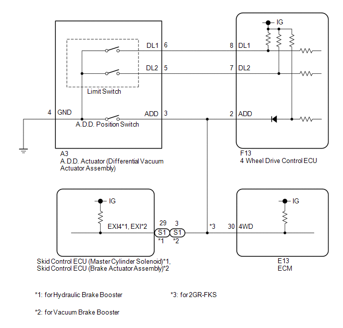
WIRING DIAGRAM
PROCEDURE
|
1. |
CHECK HARNESS AND CONNECTOR (4 WHEEL DRIVE CONTROL ECU - DIFFERENTIAL VACUUM ACTUATOR ASSEMBLY) |
(a) Disconnect the F13 4 wheel drive control ECU connector.
(b) Disconnect the A3 A.D.D. actuator (differential vacuum actuator assembly) connector.
(c) for Hydraulic Brake Booster:
Disconnect the S1 skid control ECU (Master Cylinder Solenoid) connector.
for Vacuum Brake Booster:
Disconnect the S1 skid control ECU (brake actuator assembly) connector.
(d) for 2GR-FKS:
Disconnect the E13 ECM connector.
(e) Measure the resistance according to the value(s) in the table below.
Standard Resistance:
|
Tester Connection |
Condition |
Specified Condition |
|---|---|---|
|
F13-8 (DL1) - A3-6 (DL1) |
Always |
Below 1 Ω |
|
F13-7 (DL2) - A3-5 (DL2) |
Always |
Below 1 Ω |
|
F13-2 (ADD) - A3-3 (ADD) |
Always |
Below 1 Ω |
|
A3-4 (GND) - Body ground |
Always |
Below 1 Ω |
|
F13-8 (DL1) or A3-6 (DL1) - Body ground |
Always |
10 kΩ or higher |
|
F13-7 (DL2) or A3-5 (DL2) - Body ground |
Always |
10 kΩ or higher |
|
F13-2 (ADD) or A3-3 (ADD) - Body ground |
Always |
10 kΩ or higher |
| NG | .gif) |
REPAIR OR REPLACE HARNESS OR CONNECTOR |
|
.gif)
|
2. |
INSPECT DIFFERENTIAL VACUUM ACTUATOR ASSEMBLY (LIMIT SWITCH AND A.D.D. POSITION SWITCH) |
|
(a) Disconnect the A.D.D. actuator (differential vacuum actuator assembly) connector. |
|
(b) for Hydraulic Brake Booster:
Disconnect the S1 skid control ECU (Master Cylinder Solenoid) connector.
for Vacuum Brake Booster:
Disconnect the S1 skid control ECU (brake actuator assembly) connector.
(c) for 2GR-FKS:
Disconnect the E13 ECM connector.
(d) Measure the voltage according to the value(s) in the table below.
Standard Voltage:
|
Tester Connection |
Switch Condition |
Specified Condition |
|---|---|---|
|
A3-6 (DL1) - Body ground |
Ignition switch ON |
10 to 14 V |
|
A3-5 (DL2) - Body ground |
Ignition switch ON |
10 to 14 V |
|
A3-3 (ADD) - Body ground |
Ignition switch ON |
10 to 14 V |
|
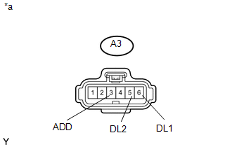
*a |
Front view of wire harness connector (to A.D.D. Actuator (Differential Vacuum Actuator Assembly)) |
| OK | |
REPLACE DIFFERENTIAL VACUUM ACTUATOR ASSEMBLY |
| NG | |
REPLACE 4 WHEEL DRIVE CONTROL ECU |
 Automatic Disconnecting Differential Motor Control Circuit Open (P17A0)
DESCRIPTION
This DTC is output when an open circuit in the A.D.D. shift motor drive circuit
is detected.
DTC No.
Detection Item
DTC Detection Condition
...
 Transfer Shift Motor Control Circuit Circuit Open (P17A8)
DESCRIPTION
This DTC is output when an open circuit in the transfer shift motor drive circuit
is detected.
DTC No.
Detection Item
DTC Detection Condition
...
Other materials:
List of storage features
Glove box
Overhead console (Access Cab and
Double Cab models)
Bottle holders
Auxiliary boxes
Front console box (separated type
front seat only)
Cup holders
CAUTION
■Items that should not be left in the storage spaces
Do not leave glasses, lighters or spray cans in the stora ...
Customize Parameters
CUSTOMIZE PARAMETERS
PROCEDURE
1. CHECK CERTIFICATION ECU (SMART KEY ECU ASSEMBLY)
HINT:
The following items can be customized.
NOTICE:
When the customer requests a change in a function, first make sure that
the function can be customized.
Record the current settings before cus ...
What to do if...
■ Instrument cluster
■ Center panel
■Warning lights
*1: Slip indicator comes on.
*2: The indicator flashes to indicate a malfunction.
GAS STATION INFORMATION
...
