Toyota Tacoma (2015-2018) Service Manual: Adjustment
ADJUSTMENT
PROCEDURE
1. REMOVE FRONT CONSOLE BOX
(See page .gif) )
)
2. ADJUST TRANSMISSION CONTROL CABLE ASSEMBLY
(a) Move the shift lever to N.
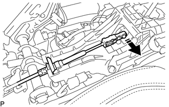
(b) Disconnect the end of the transmission control cable assembly from the transmission floor shift assembly.
 Text in Illustration
.png) |
Disconnect in this Direction |
|
(c) Push the 2 claws together at the top of the transmission control cable lock piece. While holding the 2 claws together, push the 2 lugs on the bottom of the lock piece toward each other and upward to pull out the lock piece. Text in Illustration
|
|
.png)
(d) Connect the end of the transmission control cable assembly to the transmission floor shift assembly.
.png) Text in Illustration
Text in Illustration
|
*1 |
Lock Piece |
|
|
Connect in this Direction |
NOTICE:
- Check that the park/neutral position switch and shift lever are in N.
- Make sure that the lock piece is pulled up.
- Push on the end of the cable all the way to the base of the transmission floor shift assembly pin.
|
(e) Push the lock piece into the adjuster case. Text in Illustration
NOTICE: Securely push in the lock piece until it locks. |
|
.png)
(f) After adjusting the shift lever position, check the operation and function of the shift lever. If there is a problem, adjust the position again.
3. INSTALL FRONT CONSOLE BOX
(See page )
 Components
COMPONENTS
ILLUSTRATION
...
 Installation
INSTALLATION
PROCEDURE
1. INSTALL TRANSMISSION CONTROL CABLE ASSEMBLY
(a) Install the transmission control cable assembly from outside the vehicle
body and attach the 3 claws of the cable retaine ...
Other materials:
Diagnosis System
DIAGNOSIS SYSTEM
1. DESCRIPTION
(a) Smart key system (for entry function) data and Diagnostic Trouble Codes (DTCs)
can be read through the vehicle Data Link Connector 3 (DLC3). In some cases, a malfunction
may be occurring in the smart key system. When the system seems to be malfunctioning,
...
Before Starting Adjustment
BEFORE STARTING ADJUSTMENT
CAUTION / NOTICE / HINT
NOTICE:
When replacing the windshield glass of a vehicle equipped with a forward recognition
camera, make sure to use a Toyota genuine part. If a non-Toyota genuine part is
used, the forward recognition camera may not be able to be installed ...
Dtc Check / Clear
DTC CHECK / CLEAR
NOTICE:
When the diagnosis system is changed from normal mode to check mode or vice versa,
all DTCs and freeze frame data recorded in normal mode are cleared. Before changing
modes, always check and make a note of DTCs and freeze frame data.
HINT:
DTCs which are sto ...
