Toyota Tacoma (2015-2018) Service Manual: Installation
INSTALLATION
PROCEDURE
1. INSTALL TRANSMISSION CONTROL CABLE ASSEMBLY
(a) Install the transmission control cable assembly from outside the vehicle body and attach the 3 claws of the cable retainer.
(b) Install the 2 nuts.
Torque:
5.5 N·m {56 kgf·cm, 49 in·lbf}
(c) Connect the transmission control cable support to the vehicle body with the nut.
Torque:
5.5 N·m {56 kgf·cm, 49 in·lbf}
|
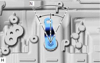
(d) Turn the transmission control shaft lever LH clockwise until it stops, and then return the transmission control shaft lever LH counterclockwise 2 notches to N. |
|
(e) Connect the transmission control cable assembly to the transmission control cable bracket with a new clip, and then connect the cable end to the transmission control shaft lever LH with the nut.
Torque:
14 N·m {143 kgf·cm, 10 ft·lbf}
2. CONNECT TRANSMISSION CONTROL CABLE ASSEMBLY
.gif)
3. INSPECT SHIFT LEVER POSITION
4. REMOVE FRONT CONSOLE BOX
(See page )
 Adjustment
ADJUSTMENT
PROCEDURE
1. REMOVE FRONT CONSOLE BOX
(See page )
2. ADJUST TRANSMISSION CONTROL CABLE ASSEMBLY
(a) Move the shift lever to N.
(b) Disconnect the end of the transmission control cab ...
 Removal
REMOVAL
PROCEDURE
1. REMOVE FRONT CONSOLE BOX
(See page )
2. DISCONNECT TRANSMISSION CONTROL CABLE ASSEMBLY
3. REMOVE TRANSMISSION CONTROL CABLE ASSEMBLY
(a) Remove the nut and c ...
Other materials:
Stereo Component Amplifier Malfunction (B15A3)
DESCRIPTION
This DTC is stored when a malfunction occurs in the stereo component amplifier
assembly.
DTC No.
DTC Detection Condition
Trouble Area
B15A3
When one of the conditions below is met:
Internal power supply malfun ...
Inspection
INSPECTION
PROCEDURE
1. INSPECT TRANSMISSION WIRE
(a) Measure the resistance according to the value(s) in the table below.
Text in Illustration
*a
Component without harness connected
(Transmission Wire)
Standard Resistance: ...
Vehicle Speed Sensor "A" No Signal (P050031)
DESCRIPTION
The speed sensor detects the wheel speed and sends the appropriate signals to
the skid control ECU. The skid control ECU converts these wheel speed signals into
a pulse signal and outputs it to the ECM via the combination meter. The ECM determines
the vehicle speed based on the fr ...
