Toyota Tacoma (2005–2015) Owners Manual: Adjusting the position of the air outlets
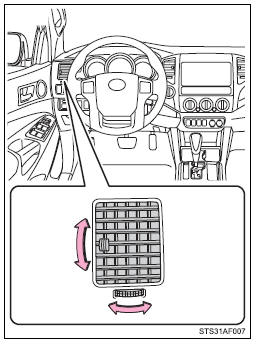
 Center outlets
Direct air flow to the left or right, up or down.
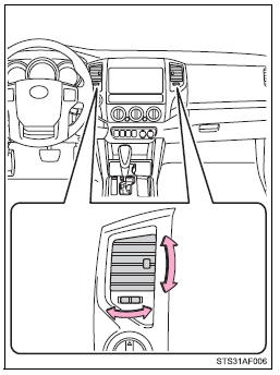
 Right and left side outlets
Direct air flow to the left or right, up or down.
Opening and closing the air outlets
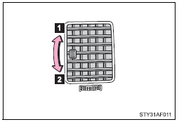
 Center outlets
 Open the vent.
 Close the vent.
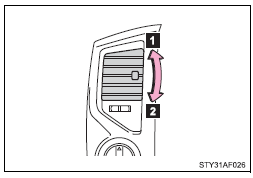
 Right and left side outlets
 Open the vent.
 Close the vent.
■For quick clearing of the windshield and side windows
Press  to turn the air conditioning
on.
to turn the air conditioning
on.
■Using the system in recirculated air mode
The windows will fog up more easily if the recirculated air mode is used for an extended period.
■When outside air temperature approaches 32°F (0°C)
The air conditioning system may not operate even when
 is pressed.
■Air conditioning filter
■When  is selected for the air
outlets used
is selected for the air
outlets used
For your driving comfort, air flowing to the feet may be warmer than air flowing to the upper body depending on the position of the temperature adjustment dial.
■Air conditioning odors
●During use, various odors from inside and outside the vehicle may enter into and accumulate in the air conditioning system. This may then cause odor to be emitted from the vents.
●To reduce potential odors from occurring: It is recommended that the air conditioning system be set to outside air mode prior to turning the vehicle off.
CAUTION
■To prevent the windshield from fogging up
Do not set the air outlet selection dial to
 during cool air operation in extremely
humid weather. The difference between the temperature of the outside air and that
of the windshield can cause the outer surface of the windshield to fog up, blocking
your vision.
during cool air operation in extremely
humid weather. The difference between the temperature of the outside air and that
of the windshield can cause the outer surface of the windshield to fog up, blocking
your vision.
NOTICE
■To prevent battery discharge
Do not leave the air conditioning system on longer than necessary when the engine is stopped.
 Air conditioning system
Adjusting the settings
■ Adjusting the temperature setting
Turn the temperature control dial clockwise (warm) or counterclockwise (cool).
If is not pressed, the system will
blow ambient ...
 Using the interior lights
Interior lights list
Interior light
Personal lights (Access Cab and
Double Cab models)
■Illuminated entry system
When the interior light switch is in the DOOR position, the interior li ...
Other materials:
Open or Short in Rear Speed Sensor RH Circuit (C1407,C1408)
DESCRIPTION
Refer to DTCs C1401 and C1402 (See page ).
DTC Code
DTC Detection Condition
Trouble Area
C1407
C1408
Either condition is met:
An open in the speed sensor signal circuit continues for 0.5
seconds or mor ...
Position Initialization Incomplete (B2343)
DESCRIPTION
This DTC is stored when the sliding roof ECU (sliding roof drive gear sub-assembly)
has not been initialized.
DTC No.
DTC Detection Condition
Trouble Area
B2343
Sliding roof ECU (sliding roof drive gear sub-assembly) has no ...
Check Bus 5 Line for Short to GND
DESCRIPTION
There may be a short circuit between one of the CAN bus lines and GND when there
is no resistance between terminal 15 (CA5H) of the central gateway ECU (network
gateway ECU) and terminal 4 (CG) of the DLC3, or terminal 16 (CA5L) of the central
gateway ECU (network gateway ECU) and ...
