Toyota Tacoma (2015-2018) Service Manual: TC and CG Terminal Circuit
DESCRIPTION
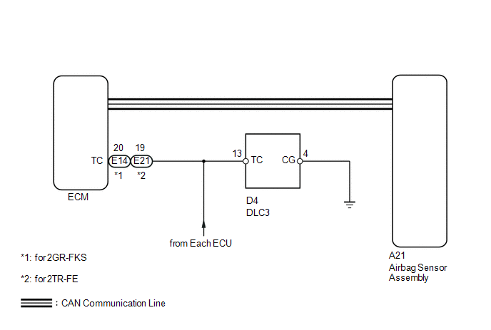
DTC output mode is set by connecting terminals TC and CG of the DLC3.
The DTCs are displayed by blinking the SRS warning light.
HINT:
- Make sure that DTCs which relate to the CAN communication system are
not output. If any of these DTCs are output, check the CAN communication
system (See page
.gif) ).
). - The DTC output mode signal is transmitted through the CAN to an ECU including the airbag sensor assembly. Thus if no systems enter DTC output mode, the ECM may have a malfunction.
- When a warning light keeps blinking, a short to ground in the wiring of terminal TC of the DLC3 or an internal ground short in each ECU is suspected.
WIRING DIAGRAM
PROCEDURE
|
1. |
CHECK HARNESS AND CONNECTOR (DLC3 - ECM) |
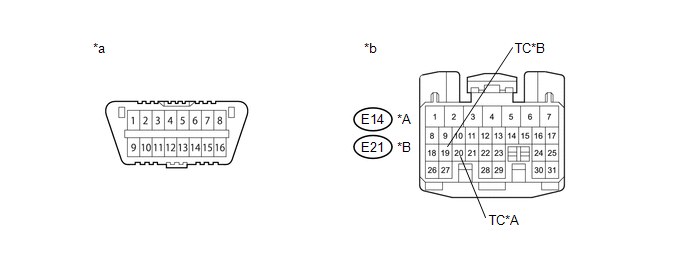 Text in Illustration
|
*A |
for 2GR-FKS |
*B |
for 2TR-FE |
|
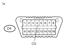
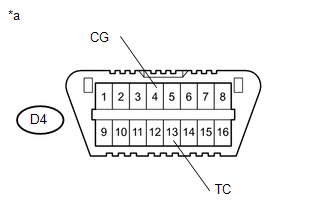
*a |
DLC3 |
*b |
Front view of wire harness connector (to ECM) |
(a) Turn the ignition switch off.
(b) Disconnect the connector from the ECM.
(c) Measure the resistance according to the value(s) in the table below.
Standard Resistance:
for 2GR-FKS|
Tester Connection |
Condition |
Specified Condition |
|---|---|---|
|
D4-13 (TC) - E14-20 (TC) |
Always |
Below 1 Ω |
|
Tester Connection |
Condition |
Specified Condition |
|---|---|---|
|
D4-13 (TC) - E21-19 (TC) |
Always |
Below 1 Ω |
| NG | .gif) |
REPAIR OR REPLACE HARNESS, ECU OR CONNECTOR |
|
.gif)
|
2. |
CHECK HARNESS AND CONNECTOR (CG OF DLC3 - BODY GROUND) |
|
(a) Measure the resistance according to the value(s) in the table below. Standard Resistance:
|
|
| NG | |
REPAIR OR REPLACE HARNESS, ECU OR CONNECTOR |
|
|
3. |
CHECK HARNESS AND CONNECTOR (TC CIRCUIT OF ECM) |
(a) Measure the resistance according to the value(s) in the table below.
Standard Resistance:
for 2GR-FKS|
Tester Connection |
Condition |
Specified Condition |
|---|---|---|
|
E14-20 (TC) - Body ground |
Always |
1 MΩ or higher |
|
Tester Connection |
Condition |
Specified Condition |
|---|---|---|
|
E21-19 (TC) - Body ground |
Always |
1 MΩ or higher |
| NG | |
REPAIR OR REPLACE HARNESS, ECU OR CONNECTOR |
|
|
4. |
CHECK DTC |
SST: 09843-18040
|
(a) Using SST, connect terminals TC and CG of the DLC3. NOTICE: Connect the terminals to the correct positions to avoid a malfunction. Text in Illustration
|
|
| A | |
USE SIMULATION METHOD TO CHECK |
| B | |
REPLACE ECM |
| C | |
REPLACE ECM |
| D | |
REPLACE AIRBAG SENSOR ASSEMBLY |
 SRS Warning Light Remains ON
DESCRIPTION
The SRS warning light is located on the combination meter assembly.
When the SRS condition is normal, the SRS warning light illuminates for approximately
6 seconds after the ignition s ...
 Center Airbag Sensor Assembly
Components
COMPONENTS
ILLUSTRATION
On-vehicle Inspection
ON-VEHICLE INSPECTION
PROCEDURE
1. INSPECT AIRBAG SENSOR ASSEMBLY (for Vehicle not Involved in Collision)
(a) Perform a diagnostic ...
Other materials:
Data List / Active Test
DATA LIST / ACTIVE TEST
1. READ DATA LIST
HINT:
Using the Techstream to read the Data List allows the values or states of switches,
sensors, actuators and other items to be read without removing any parts. This non-intrusive
inspection can be very useful because intermittent conditions or sig ...
Pressure Control Solenoid "A" Circuit Open (P074513)
DESCRIPTION
Changing from 1st to 6th is performed by the ECM turning shift solenoid valves
SL1, SL2, SL3 and SL4 on and off. If an open or short circuit occurs in any of the
shift solenoid valves, the ECM controls the remaining normal shift solenoid valves
to allow the vehicle to be operated ...
Problem Symptoms Table
PROBLEM SYMPTOMS TABLE
Use the table below to help determine the cause of problem symptoms. If multiple
suspected areas are listed, the potential causes of the symptoms are listed in order
of probability in the "Suspected Area" column of the table. Check each symptom by
checking the ...
