Toyota Tacoma (2005–2015) Owners Manual: Air conditioning system
Adjusting the settings
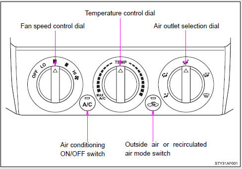
■ Adjusting the temperature setting
Turn the temperature control dial clockwise (warm) or counterclockwise (cool).
If  is not pressed, the system will
blow ambient temperature air or heated air.
is not pressed, the system will
blow ambient temperature air or heated air.
For quick cooling, turn the temperature control dial to the MAX A/C position.
The air conditioning will automatically turn on and the air intake selector will be set to recirculated air mode.
■ Adjusting the fan speed
Turn the fan speed control dial clockwise (increase) or counterclockwise (decrease).
Set the dial to OFF to turn the fan off.
■ Selecting the air outlet
Set the air outlet selection dial to an appropriate position.
The positions between the air outlet selections shown below can also be selected for more detailed adjustment.
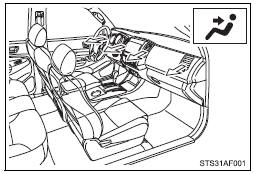
When the dial is set to  , air flows
to the upper body.
, air flows
to the upper body.
 Double Cab models only
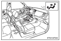
When the dial is set to  , air flows
to the upper body and feet.
, air flows
to the upper body and feet.
 Double Cab models only
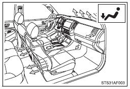
When the dial is set to  , air flows
to the feet.
, air flows
to the feet.
 Double Cab models only
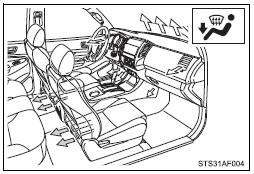
When the dial is set to  , air flows
to the feet and the windshield defogger operates.
, air flows
to the feet and the windshield defogger operates.
The air intake selector is automatically set to outside air mode.
In this position, the air intake selector cannot be changed to the recirculated air mode.
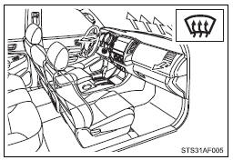
When the dial is set to  , air flows
to the windshield and side windows.
, air flows
to the windshield and side windows.
The air intake selector is automatically set to outside air mode.
In this position, the air intake selector cannot be changed to the recirculated air mode.
■ Switching between outside air and recirculated air modes
Press  .
.
The mode switches between  (outside
air mode) and
(outside
air mode) and  (recirculated air mode)
each time the switch is pressed.
(recirculated air mode)
each time the switch is pressed.

 Adjusting the position of the air outlets
Center outlets
Direct air flow to the left or right, up or down.
Right and left side outlets
Direct air flow to the left or right, up or down.
Opening and closing the air outlets
Center ou ...
Other materials:
Installation
INSTALLATION
PROCEDURE
1. INSTALL NO. 1 ULTRASONIC SENSOR
HINT:
Use the same procedure for both sides.
(a) Engage the 4 claws to install the 4 No. 1 ultrasonic sensors as shown in
the illustration.
2. INSTALL REAR BUMPER EXTENSION LH (w/ Towing Package)
(See page )
3. INSTALL REAR BUMPE ...
Installation
INSTALLATION
PROCEDURE
1. INSTALL FRONT CONSOLE BOX (for Automatic Transmission)
(a) When installing a new front console box:
Text in Illustration
*a
Runner Portion
*b
Cut Off
(1) Usin ...
Disassembly
DISASSEMBLY
PROCEDURE
1. INSPECT PROPELLER SHAFT UNIVERSAL JOINT SPIDER BEARING
(a) Check the spider bearings for wear and damage.
(b) Check each spider bearings axial play by turning the yoke while holding the
shaft tightly.
Maximum bearing axial play:
0 to 0.05 mm (0 to 0.00197 in.)
If t ...
