Toyota Tacoma (2015-2018) Service Manual: System Diagram
SYSTEM DIAGRAM
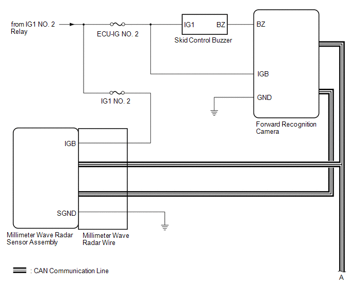
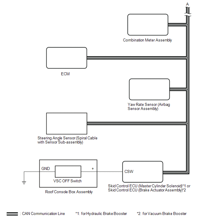 Communication Table
|
Sender |
Receiver |
Signal |
Line |
|---|---|---|---|
|
Millimeter Wave Radar Sensor Assembly |
Forward Recognition Camera |
|
CAN |
|
Skid Control ECU (Master Cylinder Solenoid)*1 or Skid Control ECU (Brake Actuator Assembly)*2 |
|
||
|
ECM |
|
||
|
Combination Meter Assembly |
|
||
|
Forward Recognition Camera |
Millimeter Wave Radar Sensor Assembly |
|
|
|
Skid Control ECU (Master Cylinder Solenoid)*1 or Skid Control ECU (Brake Actuator Assembly)*2 |
Millimeter Wave Radar Sensor Assembly |
|
|
|
Forward Recognition Camera |
|
||
|
Combination Meter Assembly |
|
||
|
Yaw Rate Sensor (Airbag Sensor Assembly) |
Millimeter Wave Radar Sensor Assembly |
|
|
|
Forward Recognition Camera |
|||
|
Main Body ECU (Multiplex Network Body ECU) |
Millimeter Wave Radar Sensor Assembly |
|
|
|
Forward Recognition Camera |
|||
|
Steering Angle Sensor (Spiral Cable with Sensor Sub-assembly) |
Millimeter Wave Radar Sensor Assembly |
|
|
|
Forward Recognition Camera |
|||
|
ECM |
Millimeter Wave Radar Sensor Assembly |
|
- *1: for Hydraulic Brake Booster
- *2: for Vacuum Brake Booster
 System Description
SYSTEM DESCRIPTION
PRE-COLLISION SYSTEM DESCRIPTION
(a) The pre-collision system uses the pre-collision warning control, pre-collision
brake assist control and pre-collision braking control to hel ...
 Customize Parameters
CUSTOMIZE PARAMETERS
NOTICE:
When the customer requests a change in a function, first make sure that
the function can be customized.
Make a note of the current settings before custom ...
Other materials:
Engine Oil Cooler
Components
COMPONENTS
ILLUSTRATION
ILLUSTRATION
ILLUSTRATION
Inspection
INSPECTION
PROCEDURE
1. INSPECT OIL COOLER ASSEMBLY
(a) Check the oil cooler assembly for damage and clogging.
If necessary, replace the oil cooler assembly.
...
Precaution
PRECAUTION
1. IGNITION SWITCH EXPRESSION
(a) The type of ignition switch used on this model differs depending on the specifications
of the vehicle.
The expressions listed in the table below are used in this section.
Expression
Ignition Switch (Position)
Engine ...
Precaution
PRECAUTION
1. IGNITION SWITCH EXPRESSIONS
(a) The type of ignition switch used on this model differs according to the specifications
of the vehicle. The expressions listed in the table below are used in this section.
Expression
Ignition Switch (Position)
Engine ...
