Toyota Tacoma (2015-2018) Service Manual: Noise Filter(for 2gr-fks)
Components
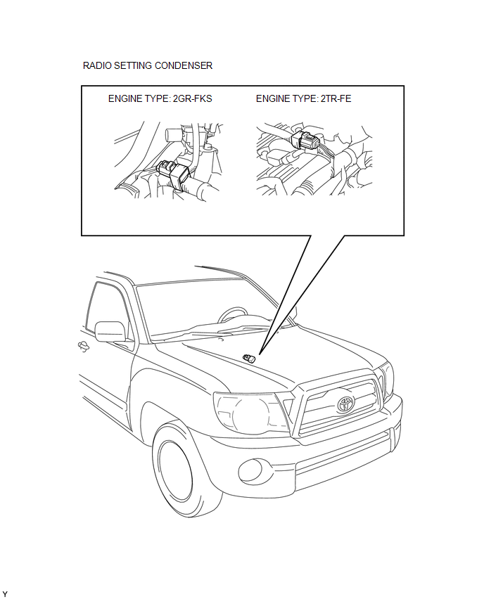
COMPONENTS
ILLUSTRATION
Removal
REMOVAL
PROCEDURE
1. DISCONNECT CABLE FROM NEGATIVE BATTERY TERMINAL
2. REMOVE V-BANK COVER
(See page .gif) )
)
3. REMOVE AIR CLEANER ASSEMBLY
(See page )
4. REMOVE RADIO SETTING CONDENSER
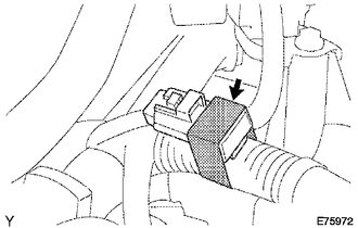
(a) Disconnect the connector.
(b) Remove the tape and the radio setting condenser.
Installation
INSTALLATION
PROCEDURE
1. INSTALL RADIO SETTING CONDENSER
.png)
(a) Connect the connector.
(b) Wind new vinyl tape around the hose and install the radio setting condenser.
2. INSTALL AIR CLEANER ASSEMBLY
(See page .gif) )
)
3. INSTALL V-BANK COVER
(See page )
4. CONNECT CABLE TO NEGATIVE BATTERY TERMINAL
Torque:
5.4 N·m {55 kgf·cm, 48 in·lbf}
 Microphone Amplifier
Components
COMPONENTS
ILLUSTRATION
*A
w/o Sliding Roof
*B
w/ Sliding Roof
*1
TELEPHONE MICROPHONE ASSEMBLY
-
...
 Noise Filter(for 2tr-fe)
Components
COMPONENTS
ILLUSTRATION
Removal
REMOVAL
PROCEDURE
1. DISCONNECT CABLE FROM NEGATIVE BATTERY TERMINAL
2. REMOVE AIR CLEANER ASSEMBLY
(See page )
3. REMOVE RADIO SETTING COND ...
Other materials:
Data List / Active Test
DATA LIST / ACTIVE TEST
1. DATA LIST
HINT:
Using the Techstream to read the Data List allows the values or states of switches,
sensors, actuators and other items to be read without removing any parts. This non-intrusive
inspection can be very useful because intermittent conditions or signals ...
Problem Symptoms Table
PROBLEM SYMPTOMS TABLE
HINT:
If a problem occurs in certain locations or at certain times of day,
check for the possibility of wave interference.
When the electrical key transmitter sub-assembly is brought near the
electrical key and TPMS receiver assembly (RF band), front outs ...
Front Evaporator Temperature Sensor
Inspection
INSPECTION
PROCEDURE
1. INSPECT COOLER THERMISTOR SENSOR
(a) Check the resistance.
(1) Measure the resistance and check the results in accordance with the
values in the table below.
Standard:
Tester Connection
Condition
...
