Toyota Tacoma (2015-2018) Service Manual: Stop Light Switch
Components
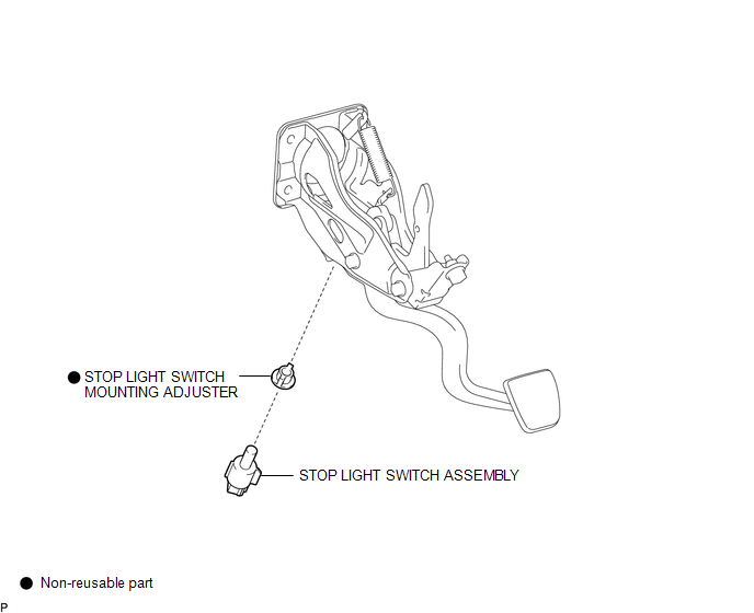
COMPONENTS
ILLUSTRATION
Inspection
INSPECTION
PROCEDURE
1. INSPECT STOP LIGHT SWITCH
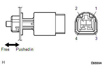
(a) Check the resistance.
(1) Measure the resistance using an ohmmeter, and check the results in accordance with the value(s) in the table below.
Standard:
|
Tester Connection |
Condition |
Specified Condition |
|---|---|---|
|
1-2 |
Switch pin free |
Below 1 Ω |
|
3-4 |
Switch pin free |
10 kΩ or higher |
|
1-2 |
Switch pin pushed in |
10 kΩ or higher |
|
3-4 |
Switch pin pushed in |
Below 1 Ω |
If the result is not as specified, replace the stop light switch assembly.
Installation
INSTALLATION
PROCEDURE
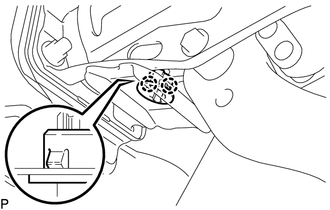
1. INSTALL STOP LIGHT SWITCH MOUNTING ADJUSTER
|
(a) Engage the 2 claws to install a new stop light switch mounting adjuster. |
|
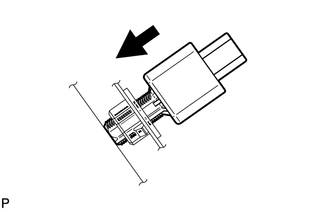
2. INSTALL STOP LIGHT SWITCH ASSEMBLY
|
(a) Insert the stop light switch assembly to the stop light switch mounting adjuster until the switch body slightly touches the brake pedal. NOTICE: Do not depress the brake pedal. |
|
|
(b) Rotate the stop light switch assembly clockwise by approximately one fourth of a rotation. Text in Illustration
|
|
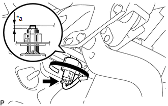
(c) Check the protrusion amount of the shaft.
Standard:
1.5 to 2.6 mm (0.0591 to 0.1024 in.)
(d) Connect the connector.
3. INSTALL LOWER NO. 1 INSTRUMENT PANEL AIRBAG ASSEMBLY
(See page .gif) )
)
Removal
REMOVAL
PROCEDURE
1. REMOVE LOWER NO. 1 INSTRUMENT PANEL AIRBAG ASSEMBLY
(See page .gif) )
)
2. REMOVE STOP LIGHT SWITCH ASSEMBLY
|
(a) Disconnect the connector. |
|
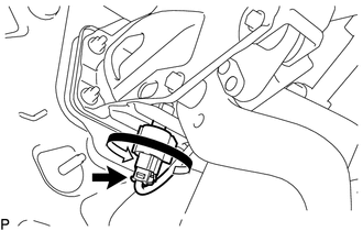
(b) Turn the stop light switch assembly counterclockwise to remove it.
3. REMOVE STOP LIGHT SWITCH MOUNTING ADJUSTER
|
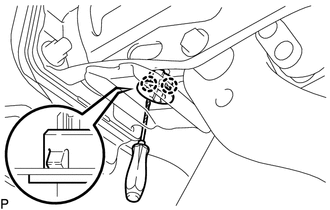
(a) Using a screwdriver, disengage 2 claws to remove the stop light switch mounting adjuster. NOTICE: The stop light switch mounting adjuster must not be reused. |
|
 Side Turn Signal Light Assembly
Components
COMPONENTS
ILLUSTRATION
Removal
REMOVAL
CAUTION / NOTICE / HINT
HINT:
Use the same procedure for both the RH and LH sides.
The procedure described below is for the ...
 Towing Tail Relay
Inspection
INSPECTION
PROCEDURE
1. INSPECT TOWING TAIL RELAY
(a) Check the resistance.
(1) Using an ohmmeter, measure the resistance between the terminals.
Standard:
Tester Conn ...
Other materials:
Installation
INSTALLATION
PROCEDURE
1. INSTALL WINDSHIELD WIPER MOTOR ASSEMBLY
(a) Apply MP grease to the crank arm pivot of the windshield wiper motor
assembly.
Text in Illustration
*1
Crank Arm Pivot
...
Adjustment
ADJUSTMENT
PROCEDURE
1. ADJUST PARK/NEUTRAL POSITION SWITCH
(a) While pushing the shift lock release button, move the shift lever to N.
(b) Remove the bolt of the park/neutral position switch.
(c) Clean the bolt and bolt hole.
(d) Apply adhesive to 2 or 3 threads on the end of the bolt.
Adhes ...
Front Evaporator Temperature Sensor
Inspection
INSPECTION
PROCEDURE
1. INSPECT COOLER THERMISTOR SENSOR
(a) Check the resistance.
(1) Measure the resistance and check the results in accordance with the
values in the table below.
Standard:
Tester Connection
Condition
...
