Toyota Tacoma (2015-2018) Service Manual: Removal
REMOVAL
PROCEDURE
1. REMOVE INTAKE AIR SURGE TANK ASSEMBLY
(See page .gif) )
)
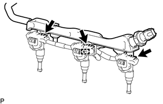
2. DISCONNECT NO. 2 FUEL TUBE SUB-ASSEMBLY
|
(a) Disengage the 2 clamps. |
|
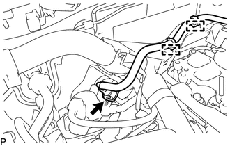
(b) Disconnect the No. 2 fuel tube sub-assembly from the fuel tube sub-assembly
(See page ).
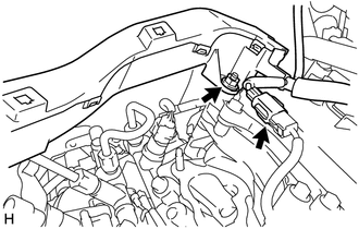
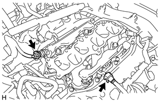
3. DISCONNECT ENGINE WIRE
|
(a) for LH Side: (1) Remove the nut and disconnect the engine wire from the cylinder head cover sub-assembly LH. (2) Disconnect the connector. |
|
|
(b) for RH Side: (1) Disengage the 2 clamps. (2) Disconnect the 13 connectors. (3) Remove the 2 bolts and disconnect the engine wire. |
|

4. REMOVE FUEL DELIVERY PIPE SUB-ASSEMBLY
NOTICE:
- Do not remove the fuel pressure sensor from the fuel delivery pipe sub-assembly.
- If a fuel pressure sensor is removed, replace the fuel delivery pipe sub-assembly (fuel pressure sensor) with a new one.
|
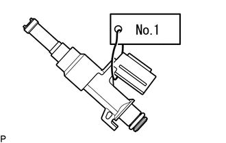
(a) Disconnect the connector. |
|
(b) Disconnect the No. 1 fuel tube sub-assembly from the fuel delivery pipe sub-assembly
(See page ).
|
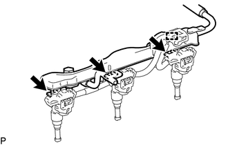
(c) Remove the 4 bolts and fuel delivery pipe sub-assembly. NOTICE: When removing the fuel delivery pipe sub-assembly, hold the pipe by both ends and pull it straight upward. |
|
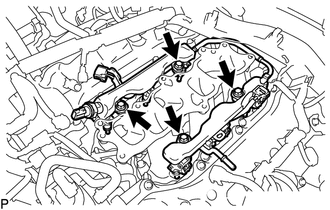
(d) Remove the 4 No. 1 delivery pipe spacers from the intake manifold.
(e) Remove the 6 injector vibration insulators from the intake manifold.
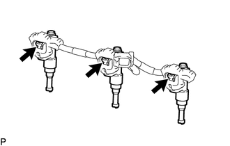
5. REMOVE FUEL INJECTOR ASSEMBLY
NOTICE:
For reinstallation, attach a tag or label to the injector shaft.
(a) for LH Side:
(1) Disengage the clamp.
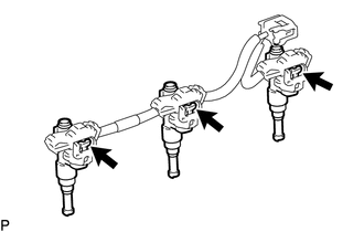
(2) Remove the 3 fuel injector assemblies with No. 5 engine wire from the fuel delivery pipe sub-assembly.
|
(3) Disconnect the 3 connectors and remove the 3 fuel injector assemblies. |
|
|
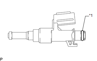
(4) Remove the O-ring from the fuel injector assembly. Text in Illustration
|
|
(b) for RH Side:
(1) Disengage the clamp.
(2) Remove the 3 fuel injector assemblies with No. 5 engine wire from the fuel delivery pipe sub-assembly.
|
(3) Disconnect the 3 connectors and remove the 3 fuel injector assemblies. |
|
|
(4) Remove the O-ring from the fuel injector assembly. Text in Illustration
|
|
 Inspection
INSPECTION
PROCEDURE
1. INSPECT FUEL INJECTOR ASSEMBLY
(a) Measure the resistance according to the value(s) in the table below.
Standard Resistance:
Tester Connection
Condi ...
 Installation
INSTALLATION
CAUTION / NOTICE / HINT
HINT:
Perform "Inspection After Repairs" after replacing the fuel injector assembly
(See page ).
PROCEDURE
1. INSTALL FUEL INJECTOR ASSEMBLY
HIN ...
Other materials:
Calibration
CALIBRATION
1. DESCRIPTION
(a) After replacing the VSC relevant components or performing "Front wheel alignment
adjustment", clearing and reading the sensor calibration data are necessary.
(b) Follow the chart to perform calibration.
Replacing Parts
Necessary Op ...
Diagnostic Trouble Code Chart
DIAGNOSTIC TROUBLE CODE CHART
Central Gateway ECU (Network Gateway ECU)
DTC Code
Detection Item
See page
B1003
ECU Malfunction
...
Terminals Of Ecu
TERMINALS OF ECU
1. BLIND SPOT MONITOR SENSOR LH (MASTER)
Terminal No.
(Symbol)
Wiring Color
Terminal Description
Condition
Specified Condition
B12-3 (BIND) - B12-10 (BLGD)
Y - W-B
Blind spot monitor ...
