Toyota Tacoma (2015-2018) Service Manual: Inspection
INSPECTION
PROCEDURE
1. INSPECT FUEL INJECTOR ASSEMBLY
(a) Measure the resistance according to the value(s) in the table below.
Standard Resistance:
|
Tester Connection |
Condition |
Specified Condition |
|---|---|---|
|
1 - 2 |
20┬░C (68┬░F) |
11.6 to 12.4 ╬® |
If the resistance is not as specified, replace the fuel injector assembly.
(b) Inspect the injection volume.
CAUTION:
This test involves high-pressure fuel and electricity. Take all precautions regarding safe handling of both the fuel and the electricity. Perform this test in a safe area, and avoid any sparks or flames. Do not smoke.
|
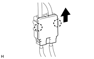
(c) Disengage the 2 claws and remove the No. 2 fuel pipe clamp. |
|
|
(d) Remove the No. 1 fuel pipe clamp. |
|
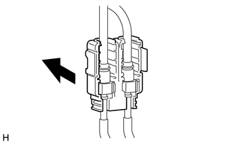
(e) Disconnect the fuel tube sub-assembly (engine compartment right side) (See
page .gif) ).
).
|
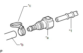
(f) Connect SST to the fuel pipe (vehicle side). Text in Illustration
SST: 09268-31014 09268-41500 09268-41700 95336-08070 |
|
|
(g) Install the O-ring to the fuel injector. Text in Illustration
|
|
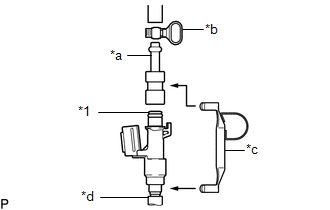
(h) Install SST and a tube to the fuel injector.
SST: 09268-31014
09268-41600
09268-41300
09268-41700
95336-08070
|
(i) Pass SST (tie band) through the loop on the handle of SST (clamp) to secure SST (clamp) to SST (adapter). Text in Illustration
SST: 09268-31014 09268-41800 NOTICE:
HINT: When removing SST (tie band), disengage the lock. |
|
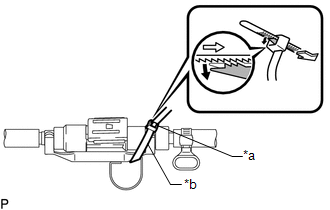
(j) Check that SST (clamp) and SST (adapter) cannot be easily separated.
(k) Install a vinyl tube to the fuel injector assembly.
NOTICE:
Install a suitable vinyl tube onto the fuel injector assembly to contain the gasoline spray.
(l) Set the fuel injector assembly in a graduated cylinder.
(m) Operate the fuel pump (See page
).
|
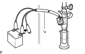
(n) Connect SST (EFI inspection wire I) to the fuel injector assembly and battery for 15 seconds, and measure the injection volume with the graduated cylinder. Test each fuel injector assembly 2 or 3 times. Text in Illustration
SST: 09842-30090 Standard injection volume: 67 to 81 cc (4.1 to 4.9 cu.in.) per 15 seconds Difference between each injector: 14 cc (0.9 cu.in.) or less NOTICE:
If the injection volume is not as specified, replace the fuel injector assembly. |
|
(o) Check for leakage.
(1) Disconnect the tester probes of SST (EFI inspection wire I) from the battery and check for fuel leaks from the fuel injector assembly.
Standard fuel drop:
1 drop or less in 20 minutes
If there is excessive leakage, replace the fuel injector assembly.
 Components
COMPONENTS
ILLUSTRATION
...
 Removal
REMOVAL
PROCEDURE
1. REMOVE INTAKE AIR SURGE TANK ASSEMBLY
(See page )
2. DISCONNECT NO. 2 FUEL TUBE SUB-ASSEMBLY
(a) Disengage the 2 clamps.
...
Other materials:
Unusual Bank Angle Detected (C1440)
DESCRIPTION
If the skid control ECU (brake actuator assembly) determines that the vehicle
is being driven at a steep bank angle, the skid control ECU (brake actuator assembly)
stores DTC C1440 while VSC operation is temporarily disabled.
This is not a malfunction if the system and sensor circu ...
Removal
REMOVAL
CAUTION / NOTICE / HINT
CAUTION:
Some of these service operations affect the SRS airbag system. Read the precautionary
notices concerning the SRS airbag system before servicing (See page
).
HINT:
Use the same procedure for the LH side and RH side.
The procedure listed be ...
Open in Bus 2 Main Bus Line
DESCRIPTION
There may be an open circuit in one of the CAN main bus lines and/or a central
gateway ECU (network gateway ECU) branch lines when the resistance between terminals
18 (CA4H) and 17 (CA4L) of the central gateway ECU (network gateway ECU) is 70 ╬®
or higher.
Detection It ...
