Toyota Tacoma (2015-2018) Service Manual: Terminals Of Ecu
TERMINALS OF ECU
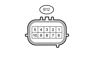
1. BLIND SPOT MONITOR SENSOR LH (MASTER)
|
Terminal No. (Symbol) |
Wiring Color |
Terminal Description |
Condition |
Specified Condition |
|---|---|---|---|---|
|
B12-3 (BIND) - B12-10 (BLGD) |
Y - W-B |
Blind spot monitor main switch indicator signal |
Blind spot monitor main switch indicator illuminated |
11 to 14 V |
|
Blind spot monitor main switch indicator not illuminated |
Below 1 V |
|||
|
B12-4 (OMIL) - B12-10 (BLGD) |
G - W-B |
Outer rear view mirror indicator power source signal RH |
Outer rear view mirror indicator illuminated |
2.5 to 7.5 V |
|
Outer rear view mirror indicator blinks |
Alternating between 0 to 7.5 V |
|||
|
Outer rear view mirror indicator not illuminated |
Below 1 V |
|||
|
B12-5 (BLB) - B12-10 (BLGD) |
LG - W-B |
IG power source signal |
Ignition switch off |
Below 1 V |
|
Ignition switch ON |
11 to 14 V |
|||
|
B12-8 (BSSW) - B12-10 (BLGD) |
GR - W-B |
Blind spot monitor main switch assembly (warning canceling switch assembly) signal |
Ignition switch ON, blind spot monitor main switch assembly (warning canceling switch assembly) on |
11 to 14 V |
|
Ignition switch ON, blind spot monitor main switch assembly (warning canceling switch assembly) off |
Below 1 V |
|||
|
B12-10 (BLGD) - Body Ground |
W-B - Body ground |
Ground |
Always |
Below 1 V |
2. BLIND SPOT MONITOR SENSOR RH (SLAVE)

|
Terminal No. (Symbol) |
Wiring Color |
Terminal Description |
Condition |
Specified Condition |
|---|---|---|---|---|
|
B13-3 (BUZ) - B13-10 (BRGD) |
R - W-B |
Rear cross traffic alert buzzer (blind spot monitor buzzer) operation signal |
Rear cross traffic alert buzzer (blind spot monitor buzzer) not sounding |
11 to 14 V |
|
Outer rear view mirror indicator blinks |
Alternating between 0 to 7.5 V |
|||
|
Rear cross traffic alert buzzer (blind spot monitor buzzer) sounding |
Alternating between 0 to 14 V |
|||
|
B13-4 (OMIR) - B13-10 (BRGD) |
SB - W-B |
Outer rear view mirror indicator power source signal LH |
Outer rear view mirror indicator illuminated |
2.5 to 7.5 V |
|
Outer rear view mirror indicator blinks |
Alternating between 0 to 7.5 V |
|||
|
Outer rear view mirror indicator not illuminated |
Below 1 V |
|||
|
B13-5 (BRB) - B13-10 (BRGD) |
LG - W-B |
IG power source signal |
Ignition switch off |
Below 1 V |
|
Ignition switch ON |
11 to 14 V |
|||
|
B13-8 (SPR) - B13-10 (BRGD)*1 |
P - W-B |
Shift position reverse switch signal |
Rear cross traffic alert function is active (vehicle is in reverse) |
11 to 14 V |
|
Rear cross traffic alert function is not active (vehicle is in position other than reverse) |
Below 1 V |
|||
|
B13-10 (BRGD) - Body Ground |
W-B - Body ground |
Ground |
Always |
Below 1 V |
- *1: for Manual Transmission
 Problem Symptoms Table
PROBLEM SYMPTOMS TABLE
HINT:
Use the table below to help determine the cause of problem symptoms. If multiple
suspected areas are listed, the potential causes of the symptoms are listed in order
...
 Diagnosis System
DIAGNOSIS SYSTEM
1. DESCRIPTION
(a) Blind spot monitor data and Diagnostic Trouble Codes (DTCs) can be read from
the Data Link Connector 3 (DLC3) of the vehicle. When the system seems to be malfun ...
Other materials:
Rear Axle Hub Bolt
Installation
INSTALLATION
PROCEDURE
1. INSTALL REAR AXLE HUB BOLT
(a) Install a new hub bolt through the axle hub.
(b) Install the washer plate, as shown in the illustration, through the hub bolt,
and install the hub bolt by tightening the hub nut.
2. APPLY HIGH TEMPERATURE GREASE
3. ...
Open in ABS Solenoid Relay Circuit (C146E,C146F)
DESCRIPTION
The ABS solenoid relay supplies power to the ABS solenoid and TRAC solenoid.
The solenoid relay is turned on 1.5 seconds after the ignition switch is turned
ON, and is turned off if an open or short in the solenoid is detected by the self
diagnosis performed when the engine starts ...
Components
COMPONENTS
ILLUSTRATION
HINT:
The following specifications are for BD22AN (w/ Differential Lock). BD22AN differentials
are equipped with M10 rear differential carrier to rear axel housing fasteners.
ILLUSTRATION
ILLUSTRATION
...
