Toyota Tacoma (2015-2018) Service Manual: Installation
INSTALLATION
CAUTION / NOTICE / HINT
HINT:
Perform "Inspection After Repairs" after replacing the fuel injector assembly
(See page .gif) ).
).
PROCEDURE
1. INSTALL FUEL INJECTOR ASSEMBLY
HINT:
Perform "Inspection After Repairs" after replacing the fuel injector assembly
(See page ).
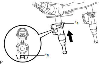
(a) Apply gasoline to new O-rings and install them to each injector.
NOTICE:
Check that there is no damage or foreign material in the groove of the injector when installing the O-rings.
|
(b) Install the fuel injector assemblies to the fuel delivery pipe sub-assembly. Text in Illustration
NOTICE:
|
|
2. INSTALL FUEL DELIVERY PIPE SUB-ASSEMBLY
NOTICE:
- Do not remove the fuel pressure sensor from the fuel delivery pipe sub-assembly.
- If a fuel pressure sensor is removed, replace the fuel delivery pipe sub-assembly (fuel pressure sensor) with a new one.
(a) Install 6 new injection vibration insulators to the intake manifold.
(b) Install the 4 No. 1 delivery pipe spacers to the intake manifold.
(c) Install the fuel delivery pipe sub-assembly (with fuel injector assembly) to the intake manifold.
NOTICE:
Be careful not to twist the O-ring.
|
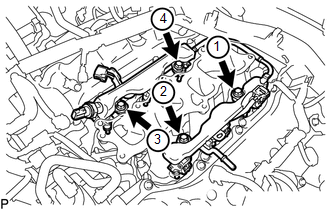
(d) Install the fuel injector assemblies to the fuel delivery pipe sub-assemblies with the 4 bolts in the order shown in the illustration. Torque: 17 N·m {173 kgf·cm, 13 ft·lbf} |
|
(e) Connect the No. 1 fuel tube sub-assembly to the fuel delivery pipe sub-assembly
(See page ).
(f) Connect the connector.
3. CONNECT ENGINE WIRE
(a) for RH Side:
(1) Connect the engine wire with the 2 bolts.
Torque:
8.0 N·m {82 kgf·cm, 71 in·lbf}
(2) Connect the 13 connectors.
(3) Engage the 2 clamps.
(b) for LH Side:
(1) Connect the connector.
(2) Connect the engine wire to the cylinder head cover sub-assembly LH with the nut.
Torque:
8.0 N·m {82 kgf·cm, 71 in·lbf}
4. CONNECT NO. 2 FUEL TUBE SUB-ASSEMBLY
(a) Connect the No. 2 fuel tube sub-assembly to the fuel tube sub-assembly (See
page ).
(b) Engage the 2 clamps.
5. INSTALL INTAKE AIR SURGE TANK ASSEMBLY
(See page )
 Removal
REMOVAL
PROCEDURE
1. REMOVE INTAKE AIR SURGE TANK ASSEMBLY
(See page )
2. DISCONNECT NO. 2 FUEL TUBE SUB-ASSEMBLY
(a) Disengage the 2 clamps.
...
 Fuel Main Valve
Components
COMPONENTS
ILLUSTRATION
Removal
REMOVAL
PROCEDURE
1. REMOVE FUEL SUCTION TUBE WITH PUMP AND GAUGE ASSEMBLY
(See page )
2. REMOVE FUEL SENDER GAUGE ASSEMBLY
3. REMOVE NO. ...
Other materials:
How To Proceed With Troubleshooting
CAUTION / NOTICE / HINT
Techstream can be used in steps 3, 6, 9 and 12.
PROCEDURE
1.
VEHICLE BROUGHT TO WORKSHOP
NEXT
2.
CUSTOMER PROBLEM ANALYSIS
...
Navigation Receiver Assembly Communication Stop Mode
DESCRIPTION
Detection Item
Symptom
Trouble Area
Navigation Receiver Assembly Communication Stop Mode
Either condition is met:
Communication stop for "Display and Navigation (AVN1)" is indicated
on the "C ...
Front Door Courtesy Switch
Inspection
INSPECTION
PROCEDURE
1. INSPECT FRONT DOOR COURTESY SWITCH
(a) Check the resistance.
(1) Measure the resistance using an ohmmeter, and check the results in accordance
with the value( s) in the table below.
Standard:
Tester Connection
Condition
...
