Toyota Tacoma (2015-2018) Service Manual: Reassembly
REASSEMBLY
CAUTION / NOTICE / HINT
HINT:
- Use the same procedure for both the LH and RH sides.
- The procedure described below is for the LH side.
PROCEDURE
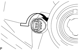
1. INSTALL CLEARANCE LIGHT BULB
(a) Install the clearance light bulb to the clearance light socket.
|
(b) Turn the clearance light socket with clearance light bulb in the direction indicated by the arrow shown in the illustration to install them. |
|
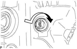
2. INSTALL FRONT TURN SIGNAL LIGHT BULB
(a) Install the front turn signal light bulb to the front turn signal light socket.
|
(b) Turn the front turn signal light socket with front turn signal light bulb in the direction indicated by the arrow shown in the illustration to install them. |
|
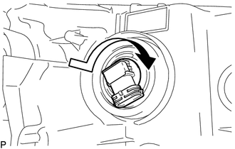
3. INSTALL NO. 2 HEADLIGHT BULB
|
(a) Turn the No. 2 headlight bulb in the direction indicated by the arrow in the illustration to install it. NOTICE: Do not touch the No. 2 headlight bulb glass. |
|
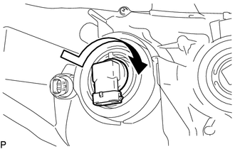
4. INSTALL NO. 1 HEADLIGHT BULB
|
(a) Turn the No. 1 headlight bulb in the direction indicated by the arrow in the illustration to install it. NOTICE: Do not touch the No. 1 headlight bulb glass. |
|
 Installation
INSTALLATION
CAUTION / NOTICE / HINT
HINT:
Use the same procedure for both the LH and RH sides.
The procedure described below is for the LH side.
PROCEDURE
1. INSTALL HEADLIGHT ...
 Headlight Dimmer Relay
Inspection
INSPECTION
PROCEDURE
1. INSPECT HEADLIGHT DIMMER RELAY
(a) Check the resistance.
(1) Measure the resistance according to the value(s) in the table below.
Standard:
...
Other materials:
Road Test
ROAD TEST
PROBLEM SYMPTOM CONFIRMATION
HINT:
The dynamic radar cruise control system has 2 cruise control modes:
constant speed control mode and vehicle-to-vehicle distance control mode.
Vehicle-to-vehicle distance control mode is selected by default when
the dyna ...
Power Supply Drive Circuit (C1257)
DESCRIPTION
The motor relay (semiconductor relay) is built into the hydraulic brake booster
and drives the pump motor based on a signal from the skid control ECU (master cylinder
solenoid).
DTC No.
DTC Detecting Condition
Trouble Areas
C1257
...
Disassembly
DISASSEMBLY
PROCEDURE
1. REMOVE REAR BUMPER HOLE COVER
(a) Disengage the 2 clips to remove the rear bumper hole cover.
2. REMOVE REAR BUMPER PAD SUB-ASSEMBLY
(a) Separate the 2 license plate light assemblies as shown in the illustr ...
