Toyota Tacoma (2015-2018) Service Manual: Disassembly
DISASSEMBLY
PROCEDURE
1. INSPECT PROPELLER SHAFT UNIVERSAL JOINT SPIDER BEARING
(a) Check the spider bearings for wear and damage.
(b) Check each spider bearings axial play by turning the yoke while holding the shaft tightly.
Maximum bearing axial play:
0 to 0.05 mm (0 to 0.00197 in.)
If the bearing axial play is greater than the maximum, replace the spider bearing.
2. REMOVE PROPELLER SHAFT UNIVERSAL JOINT SPIDER BEARING
|
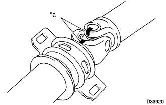
(a) Place matchmarks on the propeller shaft and universal joint yoke. Text in Illustration
|
|
|
(b) Using a brass bar and hammer, slightly tap in the spider bearing outer races. |
|
(c) Using needle-nose pliers, remove the 4 snap rings from the grooves.
|
(d) Clamp the propeller shaft in a vise between aluminum plates. NOTICE: Do not overtighten the vise. |
|
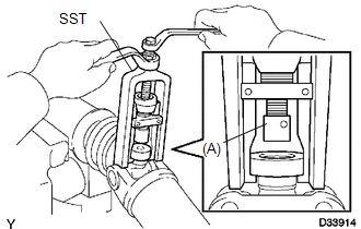
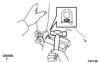
(e) Using SST, push the spider bearing out of the propeller shaft.
SST: 09332-25010
HINT:
Sufficiently raise the part indicated by (A) so that it does not come into contact with the spider bearing.
|
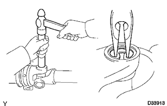
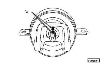
(f) Clamp the pushed out spider bearing outer race in a vise and tap the propeller shaft to remove the spider bearing. Text in Illustration
NOTICE: Do not tap the shaft. HINT: Remove the spider bearing from the opposite side of the spider using the same procedure. |
|

(g) Separate the propeller with center No. 2 support bearing assembly from the propeller shaft assembly.
|
(h) Reinstall the 2 removed spider bearings to the spider and clamp the spider bearings in a vise. NOTICE: Do not overtighten the vise. |
|

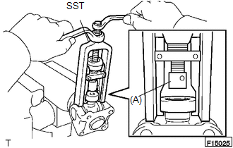
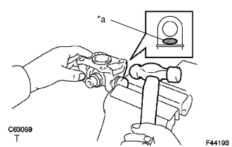
(i) Using SST, push the spider bearing out of the yoke.
SST: 09332-25010
HINT:
Sufficiently raise the part indicated by (A) so that it does not come into contact with the spider bearing.
|
(j) Clamp the pushed out spider bearing outer race in a vise and tap off the yoke with a hammer. Text in Illustration
|
|

(k) Remove the spider.
3. REMOVE PROPELLER SHAFT UNIVERSAL JOINT SPIDER BEARING
|
(a) Place matchmarks on the flange yoke and sleeve yoke. Text in Illustration
|
|

|
(b) Using a brass bar and hammer, slightly tap in the spider bearing outer races. |
|
.png)
(c) Using needle-nose pliers, remove the 4 snap rings from the grooves.
|
(d) Clamp the propeller shaft in a vise between aluminum plates. NOTICE: Do not overtighten the vise. |
|
(e) Using SST, push the spider bearing out of the propeller shaft.
SST: 09332-25010
HINT:
Sufficiently raise the part indicated by (A) so that it does not come into contact with the spider bearing.
|
(f) Clamp the pushed out spider bearing outer race in a vise and tap the propeller shaft to remove the spider bearing. Text in Illustration
NOTICE: Do not tap the shaft tube. HINT: Remove the spider bearing from the opposite side of the spider using the same procedure. |
|
(g) Separate the flange yoke and spider from the propeller shaft.
|
(h) Reinstall the 2 removed spider bearings to the spider and clamp the spider bearings in a vise. NOTICE: Do not overtighten the vise. |
|

(i) Using SST, push the spider bearing out of the yoke.
SST: 09332-25010
HINT:
Sufficiently raise the part indicated by (A) so that it does not come into contact with the spider bearing.
|
(j) Clamp the pushed out spider bearing outer race in a vise and tap off the yoke with a hammer. Text in Illustration
|
|
(k) Remove the spider.
4. REMOVE CENTER NO. 2 SUPPORT BEARING ASSEMBLY
(a) Fix the yoke at the center No. 2 support bearing assembly section in a vise between aluminum plates.
NOTICE:
Do not overtighten the vise.
(b) Using a chisel and a hammer, loosen the staked part of the lock nut.
(c) Remove the lock nut and plate washer.
|
(d) Place matchmarks on the universal joint yoke and propeller shaft with center bearing assembly. Text in Illustration
|
|
(e) Using a brass bar and hammer, remove the universal joint yoke, washer and center No. 2 support bearing assembly from the propeller shaft with center bearing assembly.
 Removal
REMOVAL
PROCEDURE
1. REMOVE PROPELLER SHAFT WITH CENTER BEARING ASSEMBLY
(a) Place matchmarks on the propeller shaft flange and differential flange.
Text in Illustration
...
 Inspection
INSPECTION
PROCEDURE
1. INSPECT PROPELLER SHAFT WITH CENTER BEARING ASSEMBLY
(a) Using a dial indicator, check the propeller shaft with center bearing assembly
runout.
Maximum runout:
0.6 mm ...
Other materials:
Turn Signal Switch Circuit
DESCRIPTION
The combination meter assembly receives the turn signal switch information and
controls the turn signal lights.
WIRING DIAGRAM
PROCEDURE
1.
READ VALUE USING TECHSTREAM (TURN SIGNAL SWITCH)
(a) Connect the Techstream to the DLC3.
(b) Turn the igni ...
Dtc Check / Clear
DTC CHECK / CLEAR
1. CHECK DTC (for TIRE PRESSURE WARNING ECU AND RECEIVER) (USING TECHSTREAM)
(a) Turn the ignition switch off.
(b) Connect the Techstream to the DLC3.
(c) Turn the ignition switch to ON.
(d) Turn the Techstream on.
(e) Enter the following menus: Chassis / Tire Pressure Monito ...
Diagnosis System
DIAGNOSIS SYSTEM
1. DESCRIPTION
(a) Smart key system (for start function) data and the Diagnostic Trouble Codes
(DTCs) can be read through the Data Link Connector 3 (DLC3) of the vehicle. When
the system seems to be malfunctioning, use the Techstream to check for malfunctions
and perform rep ...
