Toyota Tacoma (2015-2018) Service Manual: Rear Speed Sensor
Removal
REMOVAL
PROCEDURE
1. PRECAUTION
NOTICE:
After turning the ignition switch off, waiting time may be required before disconnecting the cable from the negative (-) battery terminal.
Therefore, make sure to read the disconnecting the cable from the negative (-) battery terminal notices before proceeding with work.
Click here .gif)
2. DISCONNECT CABLE FROM NEGATIVE BATTERY TERMINAL
NOTICE:
When disconnecting the cable, some systems need to be initialized after the cable is reconnected.
Click here
3. REMOVE REAR SPEED SENSOR
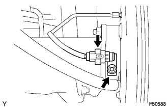
(a) Disconnect the speed sensor connector.
(b) Remove the nut and speed sensor rear.
NOTICE:
- Do not attach any foreign matter to the sensor tip.
- Ensure that no foreign matter enters the sensor installation hole.
Installation
INSTALLATION
PROCEDURE
1. INSTALL REAR SPEED SENSOR
.png)
(a) Install the rear speed sensor with the nut.
Torque:
8.0 N·m {82 kgf·cm, 71 in·lbf}
NOTICE:
Make sure that the sensor tip is clean.
(b) Connect the speed sensor connector.
2. CONNECT CABLE TO NEGATIVE BATTERY TERMINAL
Torque:
5.4 N·m {55 kgf·cm, 48 in·lbf}
NOTICE:
When disconnecting the cable, some systems need to be initialized after the cable is reconnected.
Click here .gif)
3. CHECK VSC SENSOR SIGNAL (for Hydraulic Brake Booster)
Click here
4. CHECK VSC SENSOR SIGNAL (for Vacuum Brake Booster)
Click here
 Multi-terrain Select Switch
Components
COMPONENTS
ILLUSTRATION
Removal
REMOVAL
PROCEDURE
1. REMOVE MULTI-TERRAIN SELECT SWITCH (DRIVE MONITOR SWITCH)
(a) Disengage the 2 claws to remove the multi-terrain ...

Other materials:
On-vehicle Inspection
ON-VEHICLE INSPECTION
CAUTION / NOTICE / HINT
CAUTION:
Be sure to correctly follow the removal and installation procedures for the front
airbag sensors.
PROCEDURE
1. INSPECT FRONT AIRBAG SENSOR (for Vehicle not Involved in Collision)
(a) Perform a diagnostic system check (See page
).
2. I ...
Certification ECU Vehicle Information Reading/Writing Process Malfunction (B15F7)
DESCRIPTION
This DTC is stored when items controlled by the certification ECU (smart key
ECU assembly) cannot be customized via the navigation system vehicle customization
screen.
HINT:
The certification ECU (smart key ECU assembly) controls the smart key system
related items that are custo ...
Check Mode Procedure
CHECK MODE PROCEDURE
1. DESCRIPTION
Check mode has a higher sensitivity to malfunctions and can detect malfunctions
that cannot be detected in normal mode. Check mode can also detect all of the malfunctions
that can be detected in normal mode. In check mode, DTCs are stored with 1 trip
detec ...
