Toyota Tacoma (2015-2018) Service Manual: Rear Power Outlet Socket
Components
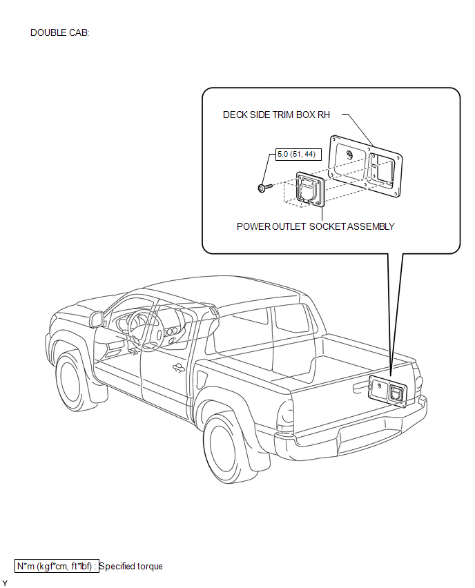
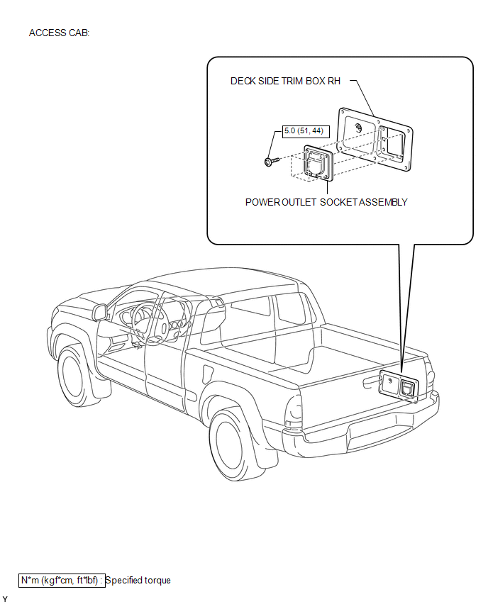
COMPONENTS
ILLUSTRATION
ILLUSTRATION
Installation
INSTALLATION
PROCEDURE
1. INSTALL POWER OUTLET SOCKET ASSEMBLY
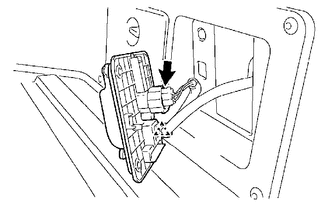
(a) Install the clamp.
(b) Connect the connector.
|
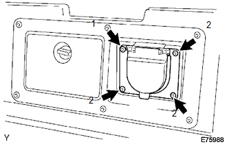
(c) Using a torx socket wrench T30, install the 4 screws and the power outlet socket assembly. Torque: 5.0 N·m {51 kgf·cm, 44 in·lbf} NOTICE: Install the screws in the order shown the illustration. |
|
2. CONNECT CABLE TO NEGATIVE BATTERY TERMINAL
Torque:
5.4 N·m {55 kgf·cm, 48 in·lbf}
Removal
REMOVAL
PROCEDURE
1. DISCONNECT CABLE FROM NEGATIVE BATTERY TERMINAL
2. REMOVE POWER OUTLET SOCKET ASSEMBLY
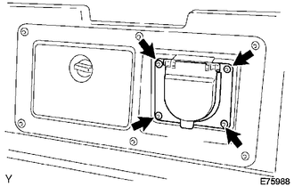
(a) Using a torx socket wrench T30, remove the 4 screws.
|
(b) Disconnect the connector. |
|
.png)
(c) Remove the clamp and the power outlet socket assembly.
 Power Outlet Socket(for Rear Side)
Components
COMPONENTS
ILLUSTRATION
*1
USB CHARGER SOCKET
-
-
Removal
REMOVAL
PROCEDURE
1. REMOVE REAR CONSOLE BOX ASSEMBLY
Click here ...
 Rear Power Outlet Switch
Components
COMPONENTS
ILLUSTRATION
Inspection
INSPECTION
PROCEDURE
1. INSPECT MAIN SWITCH ASSEMBLY
(a) Check the main switch assembly.
(1) Measure the resistance according to ...
Other materials:
Steering Pad Switch Circuit
DESCRIPTION
The forward recognition camera receives a lane departure alert switch signal
from the steering pad switch assembly.
WIRING DIAGRAM
for 2TR-FE
for 2GR-FKS
CAUTION / NOTICE / HINT
NOTICE:
The vehicle is equipped with a Supplemental Restraint System (SRS) which includes
compo ...
Manual Transmission Oil
Components
COMPONENTS
ILLUSTRATION
On-vehicle Inspection
ON-VEHICLE INSPECTION
PROCEDURE
1. INSPECT MANUAL TRANSMISSION OIL
(a) Park the vehicle on a level surface.
(b) Remove the transmission filler plug and gasket.
(c) Check that the oil level is between 0 to 5 mm (0 to 0 ...
Inspection
INSPECTION
PROCEDURE
1. INSPECT WATER INLET WITH THERMOSTAT SUB-ASSEMBLY
HINT:
The valve opening temperature is inscribed on the water inlet with thermostat
sub-assembly.
(a) Immerse the thermostat in the water, then heat the water gradually.
CAUTION:
Do not your hands into the wa ...
